Scope of supply, Connections and interfaces, Status displays – Lenze EVF9383 User Manual
Page 58
l
58
EDKVF9383 DE/EN/FR 4.0
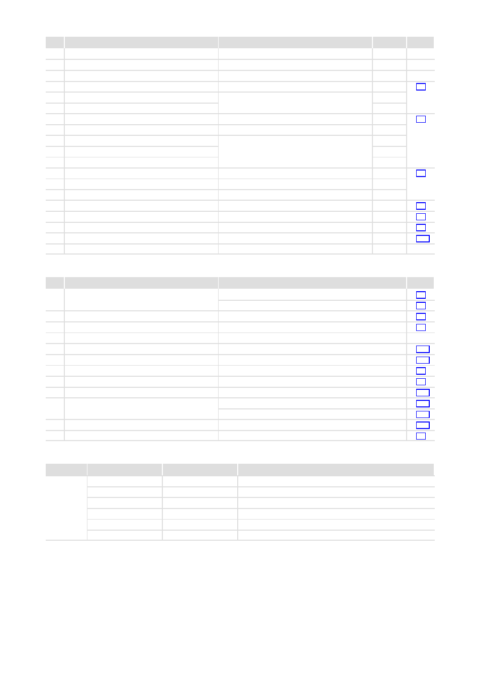
Scope of supply
Description
Use
Amount
0
9300 vector frequency inverter ˘ master
1
1
9300 vector frequency inverter ˘ slave
1
2
Mounting Instructions
1
3
Mounting rail
4
^ 78
4
Hexagon socket screw M8 × 25 mm
Fastening of the controller with the mounting rail
3 on the mounting plate
24
5
Spring washer M8
24
6
DC busbar for +U
G
+U
G
connection between master and slave
1
^ 82
7
DC busbar for −U
G
−U
G
connection between master and slave
1
8
Distance sleeve M8
Fastening of the DC busbars
6 7 in the master
and slave
6
9
Hexagon socket screw M8 × 45 mm
6
:
Plain washer M8
6
;
EMC shield sheet for shielded control cables
1
^ 95
<
Recessed head screw M4 × 12 mm
Fastening of EMC shield sheet
5
2
=
Shield clip
Connection of the cable shields to the shield sheet
3
>
4−pole terminal strip
Safety relay K
SR
at X11
1
^ 97
?
7−pole terminal strip
Digital inputs and outputs at X5
2
^ 95
@
4−pole terminal strip
Analog inputs and outputs at X6
2
^ 95
.
3−pole terminal strip
System bus (CAN) at X4
1
^ 103
/
Protective cover
Protection for unused Sub−D sockets
4
Connections and interfaces
Description
Function
Power terminals
Controller mains connection for 400 V
^ 86
Controller mains connection for 500 V
^ 87
Power terminals
Connection to the DC bus
^ 88
Power terminals
Motor connection
^ 91
x1
Control interface
Plug−in station, e.g. for keypad
X3
Jumper
Setting of analog input signal at X6/1, X6/2
^ 102
X4
Control terminals
System bus (CAN)
^ 103
X5
Control terminals
Digital inputs and outputs
^ 95
X6
Control terminals
Analog inputs and outputs
^ 95
X8
Sub−D socket
Incremental encoder input
^ 105
X9
Sub−D socket
Incremental encoder input
^ 106
Digital frequency input
^ 107
X10 Sub−D socket
Digital frequency output
^ 107
X11 Control terminals
Safety relay K
SR
^ 97
Status displays
Position
LED red
LED green
Operating status
Off
On
Controller is enabled
On
On
Mains is switched on and automatic start is inhibited
Off
Blinking slowly
Controller is inhibited
Off
On
Motor data identification is active
Blinking quickly
Off
Undervoltage or overvoltage
Blinking slowly
Off
Active fault
0Fig. 0Tab. 0