Drive control & communication, 2 drive control - register #1 – Lenze MC Series Drives User Manual
Page 16
RG-MCMOD
12
Drive Control & Communication
5.2 Drive Control - Register #1
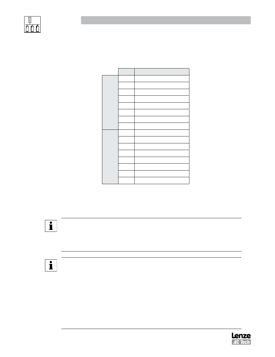
Table 8 illustrates the Data format of Register #1, Drive Control.
Table 8: Drive Control - Register #1
Bit
Command
Data Low Byte
0
UPDATE BUFFERS
1
LOCK SECURITY
2
STOP DRIVE
3
START DRIVE
4
UNUSED
5
UNUSED
6
SET REVERSE
7
SET FORWARD
Data High Byte
8
AUTO MODE
9
MANUAL MODE
10
UNUSED
11
UNUSED
12
UNUSED
13
UNUSED
14
UNUSED
15
UNUSED
The appropriate bit is set to 1. For example, to stop the drive bit two is set (send 0004H). To start the drive
send 0008H. Setting update buffers bit, enables to start the drive using downloaded data. Locking security
disables the serial drive control, the communications watchdog timer and prevents any further writing to
control or parameter registers.
NOTE 1 - Drive Control
• During each write to Register #1 only one bit should be set in the drive control word.
• If more than 1 bit is set, the drive responds to stop bit only.
• If stop bit is not set, but more than 1 bit is set, drive responds with exception 04.
NOTE 2 - Drive Family
• The QC and DL Series drives return 64 (40H)
• The MC Series drives return 65 (41H)
• The SC Series drives return 66 (42H)
• The MCH Series drives return 68 (44H)
• The
smd Series drives return 69 (45H)
• The TC Series drives return 70 (46H)
• The
Tmd Series drives return 71 (47H)
• The SMV Series drives return 72 (48H)