Commissioning, 3 display – Lenze SV SMV additional I-O module User Manual
Page 13
ALSV01B
10
Commissioning
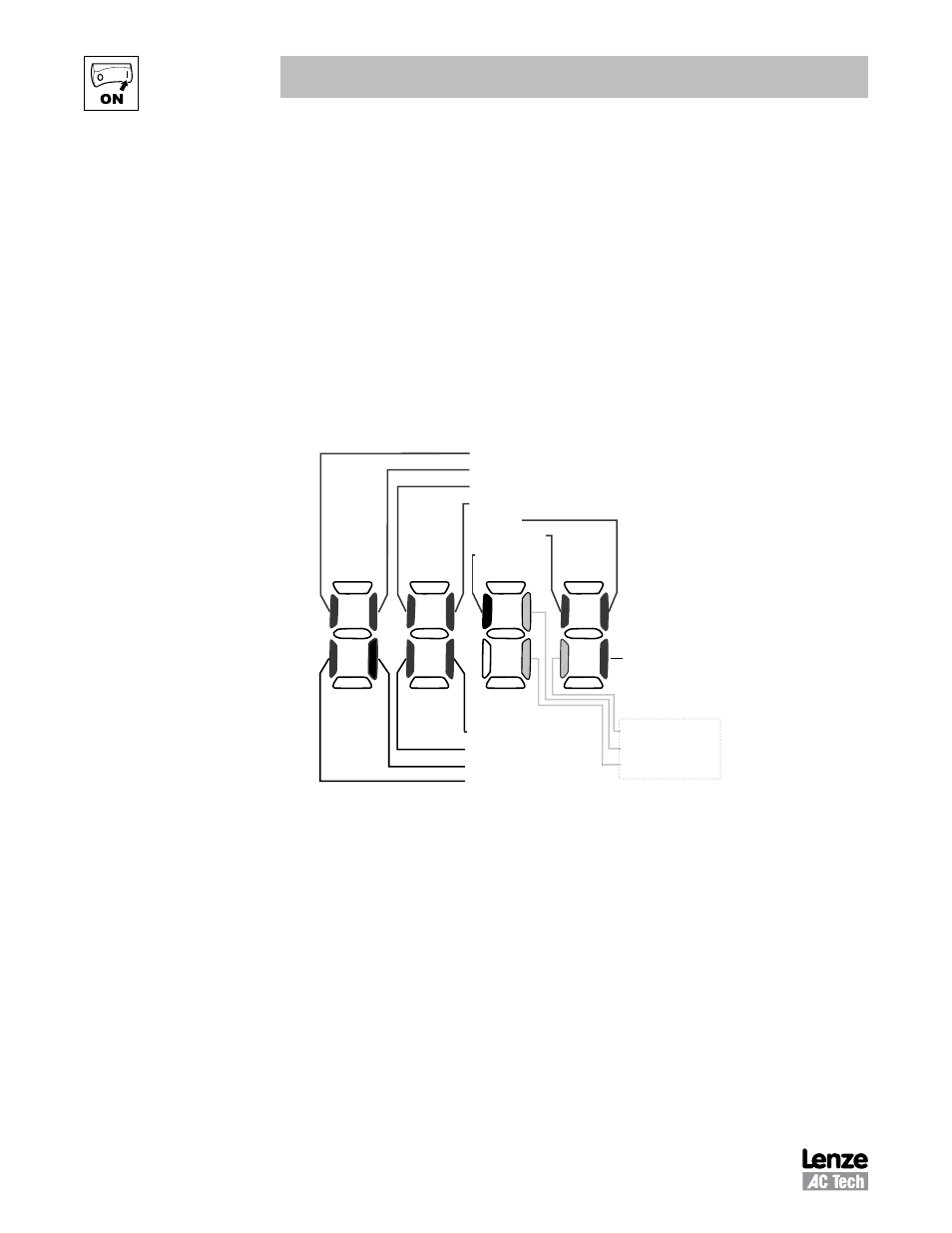
4.3 Display
Parameter P530 allows monitoring of the control terminal points and common drive conditions.
An illuminated LED segment indicates:
• the protective circuit is active (LED 1)
• the Logic Assertion Switch is set to High (+)
• input terminal is asserted (LED 2)
• output terminal is energized (LED 4)
• the Charge Relay is not a terminal, this segment will be illuminated when the Charge Relay is energized
(LED 4).
Input 13C
Input 13A
Factory Reserved
Protective Diagnostic
Current Limit Diagnostic
Logic Assertion Switch
Input 1
Input 13B
Relay
Output 14
Input 13D*
* Input 13D available on 15-60HP (11-45kW) models only
LED #
1
2
3
4
Charge
Relay
Auxiliary Relay
Input 13F
Input 13E
Additional I/O Module only
Figure 6: Status Indicators
See also other documents in the category Lenze Hardware:
- ESMD smd tmd remote keypad (4 pages)
- EPM Programmer EEPM1RA (114 pages)
- ESMDC (36 pages)
- SMD Frequency Inverter 0.37kW-22kW (116 pages)
- SMD Frequency Inverter: Basic I/O with CANopen 0.25kW-4.0kW (36 pages)
- SMD 0-25kW-4-0kW (112 pages)
- smd Series Drives (32 pages)
- ESV SMV remote keypad H0 (2 pages)
- ESV SMV remote keypad H1 (2 pages)
- EEPM1RA EPM (26 pages)
- SMVector RS-485 LECOM (29 pages)
- E84AYM10S (4 pages)
- E84AYCET EtherCAT MCI module (109 pages)
- EZAMBKBM (6 pages)
- E84AYCEC (89 pages)
- ERBPxxxRxxxx Brake resistor 200W-300W (134 pages)
- E84AYCPM (115 pages)
- E84AYCEO (165 pages)
- E84AYCER (94 pages)
- E84AVSCx 8400 StateLine C (76 pages)
- EZVxxxx-000 Power supply unit AC 230V 5A-20A (62 pages)
- E84AYCIB (75 pages)
- E82ZWBRB (48 pages)
- EZVxx00−001 Power supply unit AC 400V 5A-20A (64 pages)
- E82ZWBRE (64 pages)
- EZAEBK1001 (94 pages)
- E94AYAE SM301 (134 pages)
- E94AYAE SM301 (74 pages)
- E94AYAE SM301 (140 pages)
- E94AZPS (114 pages)
- E94AYCIB (78 pages)
- E94AYCIB (124 pages)
- E94AZEX100 (84 pages)
- EZS3-xxxA200 Sinusoidal filter 115-150A (44 pages)
- E94AZHA0051 (104 pages)
- E94AZCDM030 (72 pages)
- EZS3-xxxA200 Sinusoidal filter 180-480A (74 pages)
- E94AYCCA (188 pages)
- E94AYCCA (114 pages)
- E94AZHB0101 (104 pages)
- E94AYCPM (114 pages)
- E94AYCPM (125 pages)
- E94AYCET (140 pages)
- E94AYCET (103 pages)