Commissioning, 2 additional i/o module parameters, Alsv01b 8 – Lenze SV SMV additional I-O module User Manual
Page 11
ALSV01B
8
Commissioning
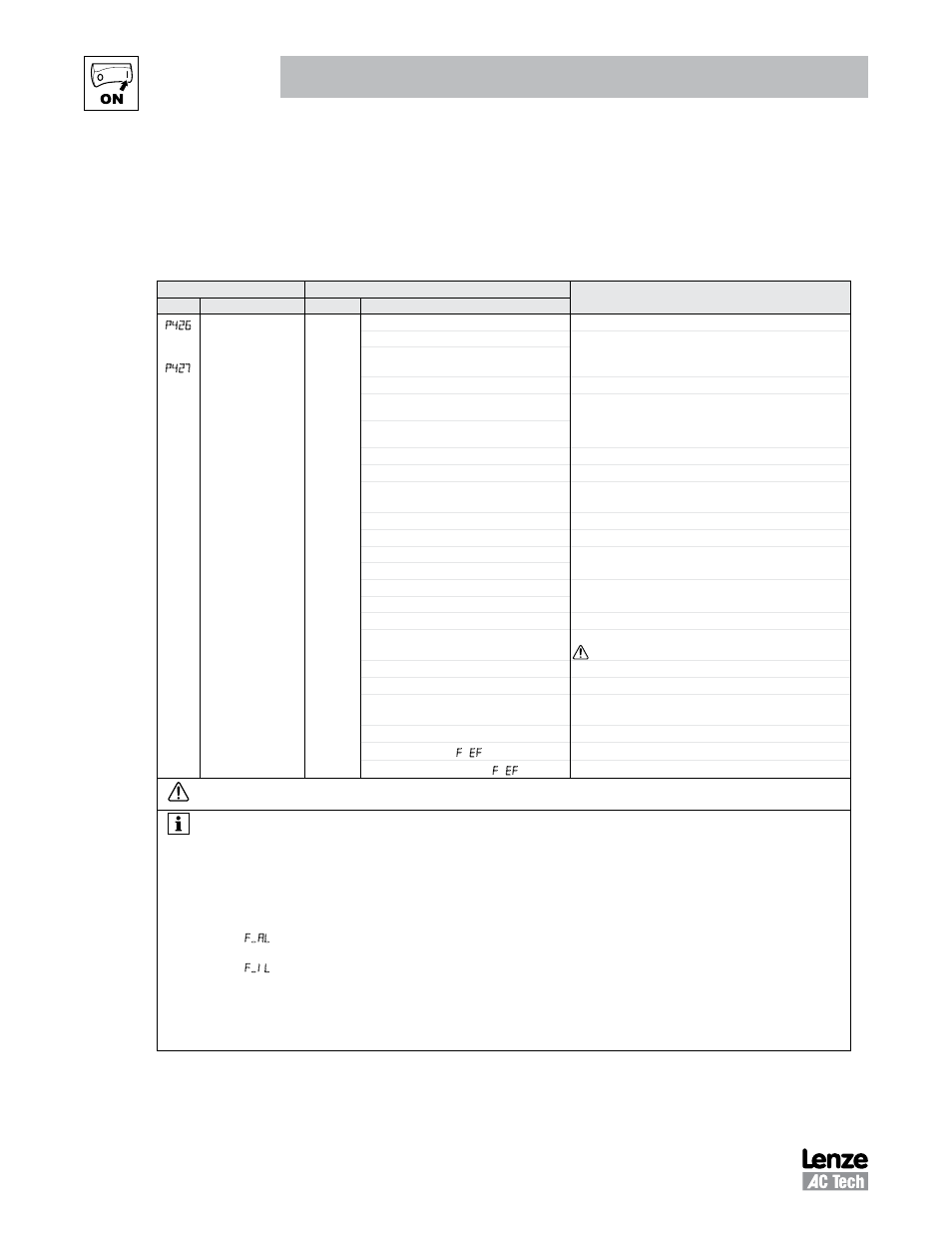
4.2 Additional I/O Module Parameters
In addition to the parameters detailed in the SMVector Frequency Inverter Operating Instructions (SV01),
installing the Additional I/O Module provides access to supplementary parameters exclusive to the Additional
I/O Module. Table 4 lists these supplementary parameters.
Table 4: Additional I/O Module Parameters
Code
Possible Settings
IMPORTANT
No.
Name
Default Selection
P426
p427
TB-13F Input
Function
TB-13G Input
Function
0
0
None
Disables input
1
AUTO Reference: 0-10 VDC
For frequency mode, see P160...P161,
For PID mode, see P204…P205,
For vector torque mode, see P330
2
AUTO Reference: 4-20 mA
RESERVED
4
AUTO Reference: MOP Up
• Normally open: Close input to increase or decrease
speed, PID setpoint or torque setpoint.
• MOP Up is not active while in STOP
5
AUTO Reference: MOP Down
6
AUTO Reference: Keypad
7
AUTO Reference: Network
8
Control Select
Use when P100 = 4, 5 to switch between terminal strip
control and local or remote keypad control.
9
Network Enable
Required to start the drive through the network.
10 Reverse Rotation
Open = Forward Closed = Reverse
11 Start Forward
Refer to Note for typical circuit
12 Start Reverse
13 Run Forward
Refer to Note for typical circuit
14 Run Reverse
15 Jog Forward
Jog Forward speed = P134
16 Jog Reverse
Jog Reverse speed = P135
Active even if P112 = 0
17 Accel/Decel #2
Refer to P125, P126
18 DC Brake
Refer to P174; close input to override P175
19 Auxiliary Ramp to Stop
Normally closed: Opening input will ramp drive to STOP
according to P127, even if P111 is set to Coast (0 or 1).
20 Clear Fault
Close to reset fault
21 External Fault F.EF
Normally closed circuit; open to trip
22 Inverse External Fault F.EF
Normally open circuit; close to trip
WARNING!
Jog overrides all STOP commands! To stop the drive while in Jog mode, the Jog input must be deactivated or a fault condition induced.
NOTE
•
When input is activated, settings 1...7 override P101
•
When TB-13A to TB-13D; TB-13F and TB-13G are configured for Auto References other than MOP, TB-13G overrides TB-13F, TB-13F
overrides TB-13D, TB-13D overrides TB-13C, TB-13C overrides TB-13B and TB-13B overrides TB-13A. Any other Auto Reference will
have priority over MOP.
•
Settings 10...14 are only valid in Terminal Strip mode (P100 = 1, 4, 5, 6)
•
If Start/Run/Jog Forward and Start/Run/Jog Reverse are both activated, drive will STOP
•
If Jog input is activated while the drive is running, the drive will enter Jog mode; when Jog input is deactivated, drive will STOP
•
An F.AL fault will occur if the Assertion Level switch (ALsw) position does not match the P120 setting and any of the digital inputs
(P121...P124, P426 ... P427) are set to a value other than 0.
•
An F.IL fault will occur under the following conditions:
- TB-13A...TB-13D and TB-13F...TB-13G settings are duplicated (each setting, except 0 and 3, can only be used once)
- One input is set to “MOP Up” and another is not set to “MOP Down”, or vice-versa.
- One input is set to 10 and another input is set to 11…14.
- One input is set to 11 or 12 and another input is set for 13 or 14.
•
TB-13D and P124 exist in 15HP (11kW) and greater drives only