2 small helical gearbox type 12.130, Small helical gearbox type 12.130, Electrical installation – Lenze 13.7xx Motors-Geared motors User Manual
Page 33: Stop
Electrical installation
Small helical gearbox type 12.130
PM motor connection
l
33
BA 13.0009 − EN 2.1
Gearbox size
Gearbox design
Without flange
Flange on the housing side
Flange on the cover side
SSN25
3 x chs.
2 x chs. / 1 x fl. head scr.
SSN31
3 x chs.
SSN40
Tab. 4
Chs.
cheese head screw with hexagon socket
Fl.
head
scr.
flat head screw
(
Stop!
For the flange mounting, seal the four threads. For this, insert the screws
with liquid sealing compound (e. g. Loctite).
5.5.2
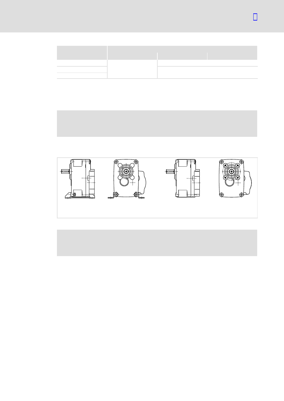
Small helical gearbox type 12.130
B3.1
B14
K12.130−15
Fig. 11
Gearbox type 12.130
(
Stop!
After the shaft sealing ring has been mounted, the motor shaft end should be
supported when the dowel pin is inserted.
ƒ
Use the screws and corresponding lock washers supplied with the mounting kit of
the motor type 13.123 for fixing the intermediate plate and the gearbox to the
motor:
– Sheet: 4 cheese head screws M5x14
– Gearbox: 4 cheese head screws M6x12
ƒ
In the case of gearbox size 12.130.60, for the purpose of centering attach the sleeve
supplied with the mounting kit to the centering of the motor bearing assembly.