Pinouts - pg 39, Rs-232 pinouts - pg 39, Rs-422 pinouts - pg 39 – B&B Electronics 3PXCC1A User Manual
Page 22: Rs-485 pinouts - pg 40
Documentation No.3PXCC1x-2x-3903
39
B&B Electronics Mfg Co – 707 Dayton Rd - PO Box 1040 - Ottawa IL 61350 - Ph 815-433-5100 - Fax 815-433-5104
B&B Electronics Ltd – Westlink Comm. Pk – Oranmore, Galway, Ireland – Ph +353 91-792444 – Fax +353 91-792445
Chapter 6: Physical Hook-up and Troubleshooting
This chapter will cover 3PXCC pinout, communication cable
data, and troubleshooting information.
Pinouts
RS-232 Pinouts
The 3PXCC Serial Cards are wired as DTE (Data Terminal
Equipment) devices. The 3PXCC Serial Cards can be connected
directly to DCE (Data Communication Equipment) devices with a
straight through cable. If you need to connect two DTE devices, you
will need a null modem cable or cross-over cable.
Table 5. RS-232 Pinout Description
RS-422 Pinouts
RS-422 mode supports transmit and receive data signals.
The pinouts of the DB-9 connector are given in Table 6. Figure 5
shows how to connect a typical RS-422/RS-485 full duplex
communication link.
Pin Name
Description
Direction
1
DCD Data
Carrier
Detect input
2
RD Receive
Data
input
3
TD Transmit
Data
output
4
DTR Data
Terminal
Ready
output
5
GND Signal
Ground
------
6
DSR Data
Set
Ready
input
7
RTS
Request to Send
output
8
CTS Clear
to
Send
input
9
RI Ring
Indicator
input
40
Documentation
No.3PXCC1x-2x-3903
B&B Electronics Mfg Co – 707 Dayton Rd - PO Box 1040 - Ottawa IL 61350 - Ph 815-433-5100 - Fax 815-433-5104
B&B Electronics Ltd – Westlink Comm. Pk – Oranmore, Galway, Ireland – Ph +353 91-792444 – Fax +353 91-792445
Pin Name Description
1
RD(A)
Receive Data A
2 TD(B)
Transmit
Data
B
3 TD(A)
Transmit
Data
A
5 GND
Signal
Ground
9
RD(B)
Receive Data B
Table 6. RS-422/RS-485 Pinout Description
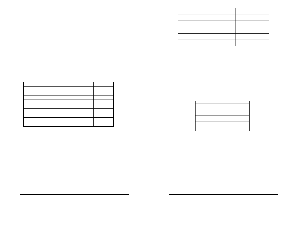
RS-485 Pinouts
RS-485 mode supports both full and half duplex
communications (transmit and receive data signals). The pinouts of
the DB-9 connector are given in Table 6 (if full duplex
communication is used). Figure 5 shows how to connect a typical
RS-422/RS-485 full duplex communication link. Figure 6 shows how
to connect a typical RS-485 half duplex communication link.
Figure 5. RS-422/RS-485 (Four Wire) Pinout Description
TD(A-) Pin 3
TD(B+) Pin 2
RD(A-) Pin 1
RD(B+) Pin 9
GND Pin 5
TD(-)
TD(+)
RD(-)
RD(+)
GND
3PXCCXX Serial Card
RS-422 Four Wire Devic