Interrupt jumper setup - pg 32 – B&B Electronics 3PXCC1A User Manual
Page 18
Documentation No.3PXCC1x-2x-3903
31
B&B Electronics Mfg Co – 707 Dayton Rd - PO Box 1040 - Ottawa IL 61350 - Ph 815-433-5100 - Fax 815-433-5104
B&B Electronics Ltd – Westlink Comm. Pk – Oranmore, Galway, Ireland – Ph +353 91-792444 – Fax +353 91-792445
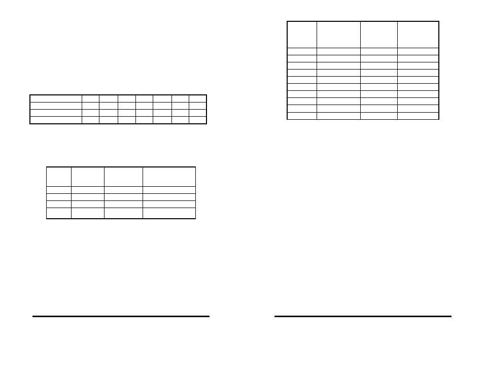
When setting the address (via the dipswitch) use the silkscreen
on the printed circuit board. This silkscreen shows a “1” and a “0” to
refer to the “on and “off” states that each switch is set to. Switch S1
configures port one (labeled J1) and, on two port cards, switch S2
configures port two (labeled J2). Least significant bit (LSB) and most
significant bit (MSB) are labeled on the card. Table 1 shows the
numerical weight and electrical connection of each switch position.
Refer to Table 2 for COM port addresses. Table 3 shows frequently
unused port addresses for applications when COM port addresses
1-4 are already used.
To install the 3PXCC card as COM1, 2, 3, or 4, follow the switch
settings shown in Table 2. To install at another address, follow the
switch settings shown in Table 3.
Table 2. Standard Port Addresses
Table 1. Address Switches
Switch
Position 7 6 5 4 3 2 1
Bus Connection SA9 SA8 SA7 SA6 SA5 SA4 SA3
Decimal Weight
512 256 128 64
32 16 8
Hex Weight
200 100 80 40 20 10 8
Base
Hex
Address
Binary
Equivalent
Switch Settings
MSB LSB
7654321
COM1
3F8 1111111000 1111111
COM2
2F8 1011111000 1011111
COM3
3E8 1111101000 1111101
COM4
2E8 1011101000 1011101
32
Documentation
No.3PXCC1x-2x-3903
B&B Electronics Mfg Co – 707 Dayton Rd - PO Box 1040 - Ottawa IL 61350 - Ph 815-433-5100 - Fax 815-433-5104
B&B Electronics Ltd – Westlink Comm. Pk – Oranmore, Galway, Ireland – Ph +353 91-792444 – Fax +353 91-792445
Table 3. Frequently Unused Port Addresses
Interrupt Jumper Setup
The IRQ is a hardware Interrupt Request line in an ISA Bus
expansion slot on a PC or AT compatible computer. The 8 bit PC
ISA slot has 8 interrupts, the 16 bit slot has another 7 since one of
the first 8 is used to link in the remaining 8. The IRQ is used by
devices to request immediate service by the main microprocessor.
When the IRQ line is set, the microprocessor stops whatever it’s
doing, saves status, checks which line was set, then jumps to code
to handle the interrupt. The processor then clears the interrupt and
returns to what it was doing before. IRQ lines are set by the internal
timer, keyboard, hard drive controller, PCI, USB controller, sound
card, serial ports, printer and more. The 3PXCC2 serial cards
include special circuitry which allows one IRQ to be shared between
the cards two ports even during simultaneous use. The software
driver must support shared IRQs for this feature to work. Both
Windows 9x and NT support shared IRQs. To configure both ports
of the card to share one IRQ, set both jumpers of JP4 to the “Share”
position. The Port 1 IRQ Select jumper should then be set to the
desired IRQ. The Port 2 IRQ Select jumper is ignored when in
shared mode.
The 3PXCC cards allow the use of interrupts (IRQ) 2, 3, 4, 5, 6,
7, 10, 11, 12, 14, and 15. Table 4 shows the standard serial port IRQ
settings. NOTE: If two ports use the same IRQ setting, both ports
cannot use the serial port at once. Only one port at a time may
communicate.
Base
Hex
Address
Binary
Equivalent
Switch
Settings
MSB LSB
7654321
I/O Space
Description
200
1000000000 1000000 game
port
208
1000001000 1000001 game
port
300
1100000000 1100000 prototype
308
1100001000 1100001 prototype
310
1100010000 1100010 prototype
318
1100011000 1100011 prototype
380
1110000000 1110000 SDLC
388
1110001000 1110001 SDLC
3A0
1110100000 1110100 bisync
com
3A8
1110101000 1110101 bisync
com