Chapter 5: communication jumper settings - pg 35, Rs-232 mode - pg 35, Rs-422 mode - pg 36 – B&B Electronics 3PXCC1A User Manual
Page 20: Rs-485 mode - pg 36
Documentation No.3PXCC1x-2x-3903
35
B&B Electronics Mfg Co – 707 Dayton Rd - PO Box 1040 - Ottawa IL 61350 - Ph 815-433-5100 - Fax 815-433-5104
B&B Electronics Ltd – Westlink Comm. Pk – Oranmore, Galway, Ireland – Ph +353 91-792444 – Fax +353 91-792445
Chapter 5: Communication Jumper Settings
This chapter will cover all of the jumper settings to set your B&B
Serial Card for the proper communications that you desire.
RS-232 Mode
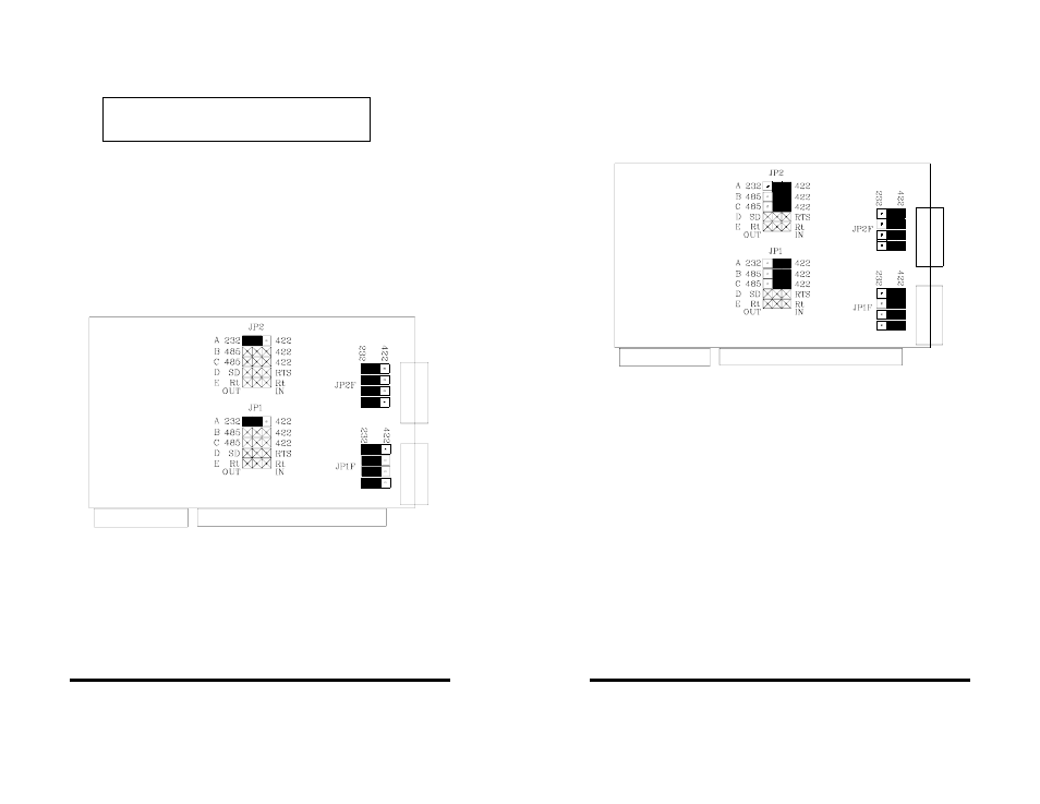
To configure a port for RS-232 mode, 5 jumpers must be
checked. The following settings will configure Port 1 as RS-232.
1. JP1A - must be set in the "232" (left) position.
2. JP1F - all four jumpers must be set in the "232" (left) position.
Jumpers JP1B - JP1E have no meaning in RS-232 mode
and may be in either position. Figure 2 shows the jumper
configuration to set both ports for RS-232 mode.
Figure 2. RS-232 Mode Jumper Settings
CAUTION: Electrostatic Sensitive Device.
Use ESD precautions for safe handling.
36
Documentation
No.3PXCC1x-2x-3903
B&B Electronics Mfg Co – 707 Dayton Rd - PO Box 1040 - Ottawa IL 61350 - Ph 815-433-5100 - Fax 815-433-5104
B&B Electronics Ltd – Westlink Comm. Pk – Oranmore, Galway, Ireland – Ph +353 91-792444 – Fax +353 91-792445
RS-422 Mode
To configure a port for RS-422 mode, 7 jumpers must be
checked. The following settings configure Port 1 as RS-422.
1.
JP1A, JP1B, JP1C - must be set in the "422" (right) position.
2.
JP1F - all four jumpers must be in the "422" (right) position.
Figure 3 shows the jumper configuration to set both ports for
RS-422 mode.
Figure 3. RS-422 Mode Jumper Settings
Note that the EIA RS-422 Specification labels data lines with
an "A" and "B" designator. Some RS-422 equipment uses a "+" and
"-" designator. In almost all cases, the "A" line is the equivalent of
the "-" line and the "B" line is the equivalent of the "+" line. More
information on RS-422 communications can be found in B&B
Electronics’ free RS-422/RS-485 Application Note.
RS-485 Mode
To configure a port for RS-485 mode, 9 jumpers must be
checked. The following settings configure Port 1 as RS-485.
1. JP1A - must be set in the "422" (right) position.
2. JP1B, JP1C - must be set in the "485" (left) position.
3. JP1D, JP1E - set to match software and installation
requirements.
4. JP1F - all four jumpers must be in the "422" (right) position.