Transceiver alignment – Kisan Electronics TPM-60 User Manual
Page 11
9
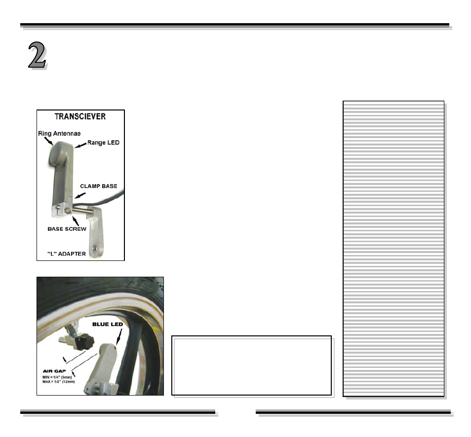
TRANSCEIVER ALIGNMENT:
At this stage of the installation, the Transceivers are mounted on the dowel pins of the front and rear
adapters such that they are lined-up with approximately 1/4” (6mm) of air-gap. And the cables are routed
for power and ground hook up.
n
Install the Mounting Adapter.
o
Slide the Transceiver over the dowel pin such that
the LED faces outboard.
p
Rotate the wheel carefully to line-up the Sensor with
the Transceiver.
q
Adjust the clamp-base to get an air-gap of 1/4”
(6mm)
r
Lightly tighten clamp-base screw with 3/32” Allen
wrench. Later on, you may have to adjust this for a final
setting.
s
Route the cables alongside brake hoses or existing
wiring harness, using wire-ties at appropriate places. In
most cases, the connector end should end up under the
seat for power and ground hook-up.
As shown here the antennae of the
Transceiver should line-up with the face of
the Sensor on the wheel – with about a 1/4”
(6mm) of air gap.
Objective is to achieve an
air-gap of 1/4” (6mm)
between the Transceiver
and the Sensor.
Check to see that after
installing the Transceiver,
the wheel is able to rotate
freely without interference.
Make sure that cables do
not touch any sharp
edges or high
temperature parts.
Later, when the rest of the installation
is completed and the system is powered,
the LED of the transceiver will flash once
every second to indicate if the Sensor is
within the acceptable range.