JUMO 902820 PROCESStemp RTD Temperature Probe for Process Technology (Also with ATEX Approval) Ex e Operating Manual User Manual
Page 5
- 4 -
Temperature class
Max. surface temperature
of the equipment
1
Ignition temperature of the
flammable materials
T1 450
°C
450 °C
T2 300
°C
300 450 °C
T3 200
°C
200 300 °C
T4 135
°C
135 200 °C
T5 100
°C
100 135 °C
T6 85
°C
85 100 °C
Table 2: Temperature classes
1
Explanation
The following safety reserves must also be complied with:
Category 1: according to EN 1127-1:1997 Item 6.4.2 (hot surfaces): the temperature of any and all surfaces of equipment … used in
Zone 0..., that come into contact with a potentially explosive atmosphere, ... must not exceed … 80 % of the ignition temperature!
Temperature class minus 20 %! An additional reduction must be applied: 10 °C for temperature classes T1 and T2, 5 °C for classes
T3 – T6.
Category 2: a safety reserve (reduction) must be applied: 10°C for temperature classes T1 – T2, 5 °C for temperature classes T3 – T6.
The surface heating itself is influenced by the design of the temperature probe, by the ambient conditions
(thermal coupling with the medium being measured) and the power that is applied. The self-heating behavior
of the thermometer is characterized by the thermowell constant SK (in °C/W), which represents the increase
in the surface temperature (in still air) above the ambient temperature as a function of the applied power.
The thermowell constant SK is determined by JUMO, and can be found in the attached technical data sheet
or on the affixed label. The user must determine whether the thermometer is suitable for the measurement
application and the connected equipment under the given conditions. The maximum permissible measured
temperature at the probe tip can be derived from the following equation: T
S
= T
K
– P
i
× SK
T
S
Maximum permissible temperature at the probe tip
T
K
Maximum permissible surface temperature, depending on the temperature class
(as in table, reduced by the safety reserve)
P
i
Power in the certified intrinsically safe circuit
SK
Thermowell constant (see technical data sheet)
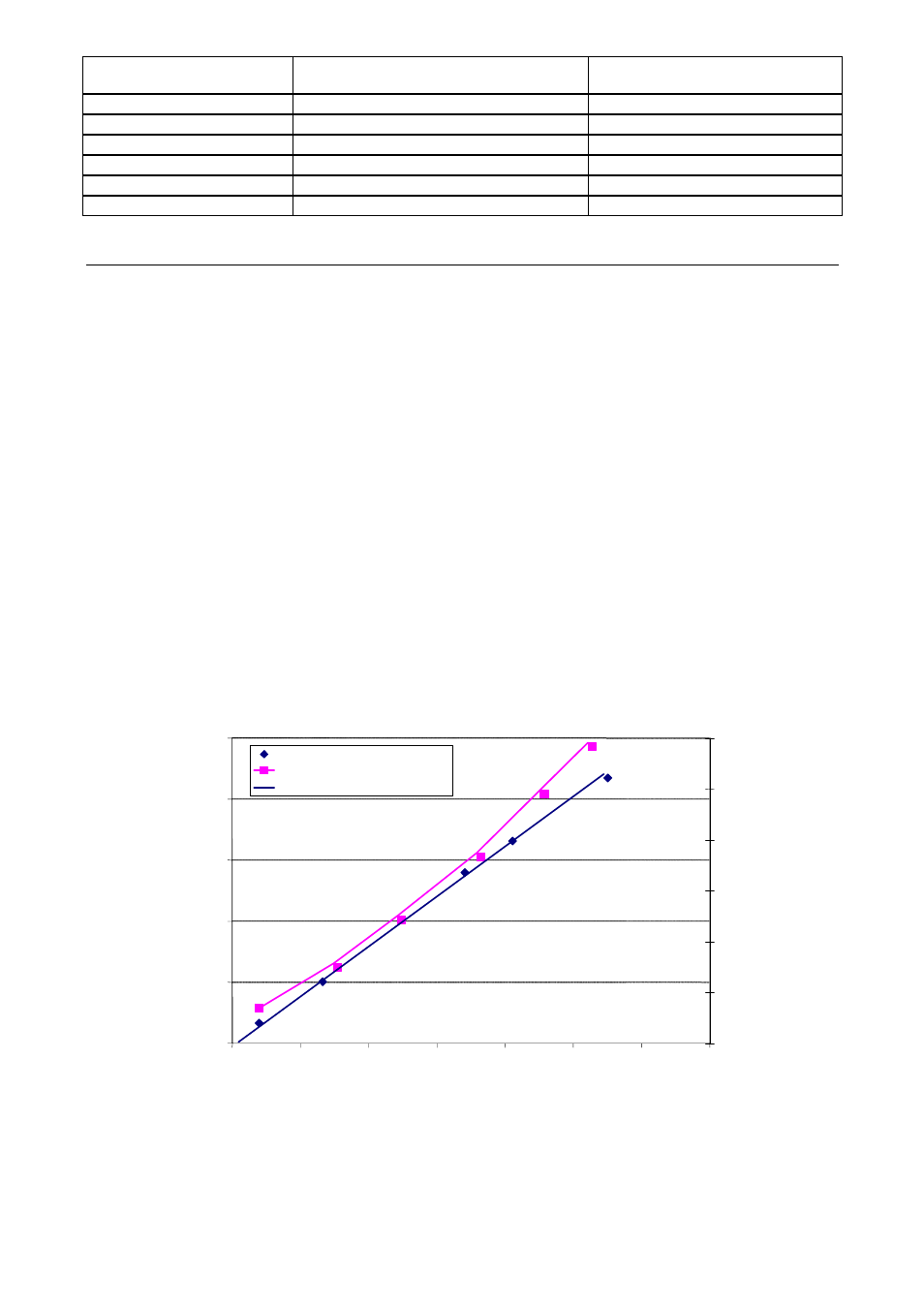
The following diagram illustrates an example of self-heating of the probe surface of a RTD temperature
probe, as a function of the applied power and thus the temperature arising within the probe. (Self-heating is
independent of the protection type, and also applies to the flameproof enclosure).
SK = 80 °C/W
0.0
50.0
100.0
150.0
200.0
250.0
0
0.5
1
1.5
2
2.5
3
3.5
Power / W
In
cr
e
a
se
in
sur
fa
c
e
t
e
mp
er
a
tu
re
/
°
C
0
100
200
300
400
500
600
In
te
rn
al
pr
ob
e t
e
m
p
er
at
ur
e /
°
C
Surface temperature
Internal temperature
Linear (surface temperature)
Figure 1 : Self-heating of a Pt100 RTD temperature probes