Loading diagrams – JUMO 909710 Screw-In Thermowells Data Sheet User Manual
Page 3
JUMO GmbH & Co. KG
Delivery address:Mackenrodtstraße 14,
36039 Fulda, Germany
Postal address: 36035 Fulda, Germany
Phone:
+49 661 6003-0
Fax:
+49 661 6003-607
E-mail:
Internet:
www.jumo.net
JUMO Instrument Co. Ltd.
JUMO House
Temple Bank, Riverway
Harlow, Essex CM20 2DY, UK
Phone: +44 1279 635533
Fax:
+44 1279 635262
E-mail:
Internet: www.jumo.co.uk
JUMO Process Control, Inc.
8 Technology Boulevard
Canastota, NY 13032, USA
Phone:
315-697-5866
1-800-554-JUMO
Fax:
315-697-5867
E-mail:
Internet: www.jumo.us
2011-11-01/00073431
Data Sheet 909710 (909721)
Page 3/6
Loading diagrams
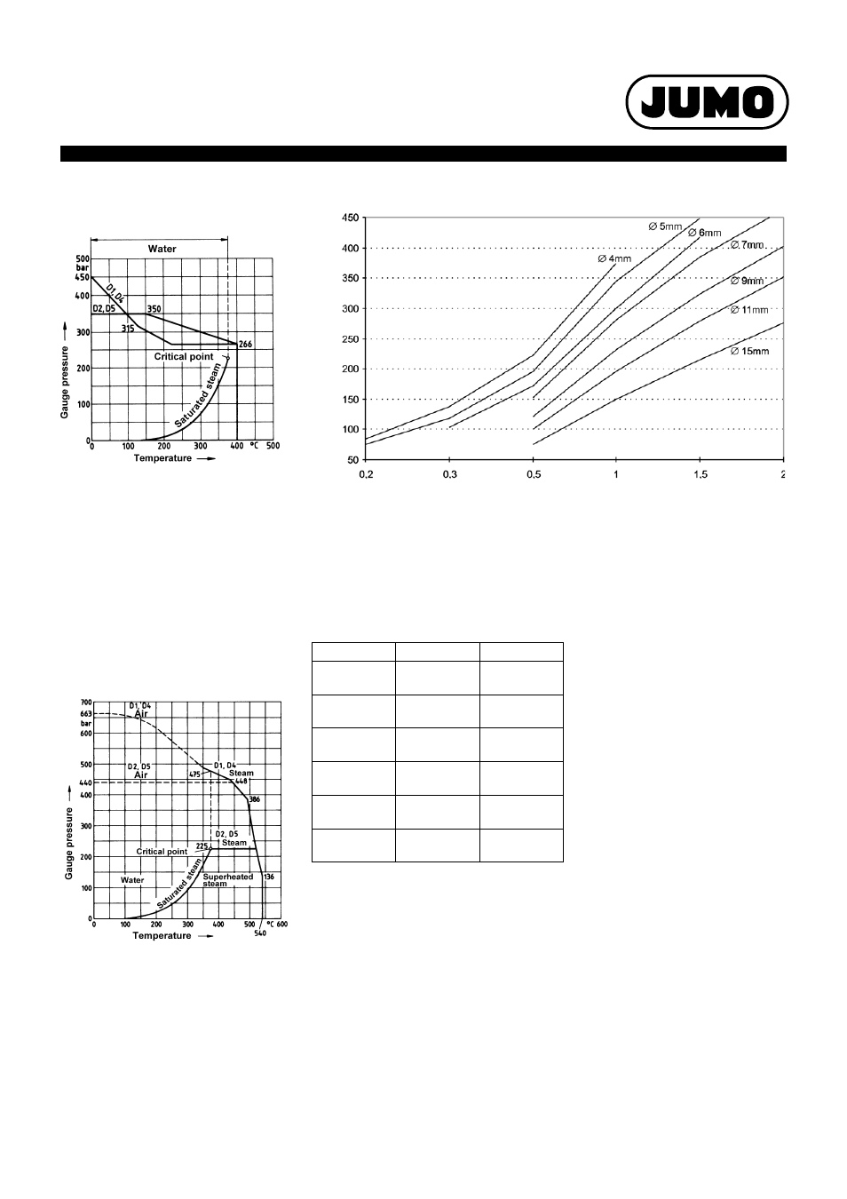
Load limits on sheaths, for various sheath dimensions
The diagram shows the load limits (guide values) for different sheath dimensions. The ma-
ximum pressure loading of cylindrical sheaths is shown in relation to the wall thickness with
different sheath diameters. The data refer to sheaths in stainless steel 1.4571, fitting length
100 mm, flow velocity 10 m/sec in air or 4 m/sec in water and a temperature range from -20
to +100 °C. A safety factor of 1.8 has been taken into account. For higher temperatures, or
different materials, the maximum pressure loading has to be reduced by the percentage valu-
es given in the table.
Loading of sheaths
Form D according to 43763
Basic type 909712/50 and /51
Sheath: st. steel X6 CrNiMoTi 17 12 2,
Material Ref. 1.4571
Sheaths D1 and D4:
Permissible flow velocity for
air, water, superhtd. steam: up to 60 m/sec
Sheaths D2 and D5:
Permissible flow velocity
for air: up to 60 m/sec
for water, superheated steam: up to 30 m/sec
Loading on sheaths
Form D according to 43763
Basic type 909712/50 and /51
Sheath: steel 13 CrMo 44,
Material Ref. 1.7335
Permissible flow velocity for
air and superheated steam: up to 60 m/sec
Loading in water: up to 450 bar
and up to 5 m/sec
Wall thickness in mm
Pr
es
sur
e
lo
adi
n
g in ba
r
Material
Temperature
Reduction
CrNi
1.4571
up to +200 °C
-10 %
CrNi
1.4571
up to +300 °C
-20 %
CrNi
1.4571
up to +400 °C
-25 %
CrNi
1.4571
up to +500 °C
-30 %
CuZn
2.0401
up to +100 °C
-15 %
CuZn
2.0401
up to +175 °C
-60 %