JUMO 603051 Surface-Mounted Thermostats, AMTHF series Data Sheet User Manual
Page 3
Data Sheet 603051
2013-03-07/00439872
Page 3/8
JUMO GmbH & Co. KG
Delivery address: Mackenrodtstraße 14
36039 Fulda, Germany
Postal address:
36035 Fulda, Germany
Phone:
+49 661 6003-0
Fax:
+49 661 6003-607
E-mail:
Internet:
www.jumo.net
JUMO Instrument Co. Ltd.
JUMO House
Temple Bank, Riverway
Harlow, Essex CM20 2DY, UK
Phone: +44 1279 635533
Fax:
+44 1279 635262
E-mail:
Internet: www.jumo.co.uk
JUMO Process Control, Inc.
6733 Myers Road
East Syracuse, NY 13057, USA
Phone: 315-437-5866
1-800-554-5866
Fax:
315-437-5860
E-mail:
Internet: www.jumousa.com
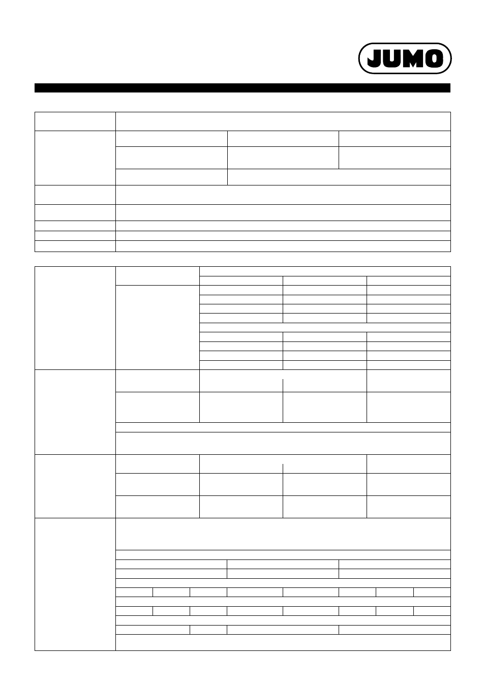
Electrical data
Operating data
Switching element
2, 3 or 4 1-pole snap switch
Microswitch with change-over contact
max. contact rating
Hysteresis
switching function
N/C contact,
terminal 2
N/O contact,
terminal 4
TR, TW
2.5%, 5%, 6%, 7%, 10%
AC 230 V +10%,
16 (3) A, cos
ϕ = 1(0.6)
DC 230 V +10%, 0.25A
AC 230 V +10%,
8 (1.5) A, cos
ϕ = 1(0.6)
DC 230 V +10%, 0.25A
TR, TW
1 %, 3 %
AC 230 V +10%, 6 (2) A, cos
ϕ = 1(0.6)
DC 230 V +10%, 0.25A
Contact reliability
To ensure high switching reliability, we recommend a minimum load of:
AC / DC = 24 V, 20 mA
Rating
surge voltage
1500 V (via the switching contacts 400 V)
Overvoltage category
II
Required fuse rating
see max. contact rating
Electrical connection
Screw connection up to 2.5 mm
2
cable cross section
Hysteresis
in % of the control /
limit value range
Switching function
with fluid-filled measuring system
Rated value
Possible process value
TR, TW
2.5
2.5 max. 3.5
serial
5
5 max. 6
on request
7
7 max. 8
on request
1
1 max. 2
Surcharge
with gas-filled measuring system
5
5 max.11
serial
6
6 max. 14
on request
10
10 max. 16
on request
3
2.5 max. 4
Surcharge
Sequential gap
for multi-pin
version
with hysteresis
Sequential gap from the scale range
Switching point accuracy
of the sequential gaps from
the scale range
minimum
maximum
1%
2.5%
3%, 5%
6%, 7%, 10%
1%
1%
2%
3%
as per
control range table
≤ 1%
≤ 1%
< 2%
< 3%
The sequential gap is specified in K in relation to the set point value of contact deck I.
Prefix - = switching prior to reaching the set point value,
Prefix + = switching after reaching the set point value.
Enter "0" for the sequential gap for a simultaneously switching version.
Switching point accuracy
in % of the control/limit
value range
Switching function
Hysteresis
in the upper third of the
scale or limit value
fluid-filled
gas-filled
TR
1%, 2.5%
5%
7%
- -
3%, 5%,
6%, 10%
± 1.5%
± 3.0%
± 4.0%
TW
1%, 2.5%
5%
7%
- -
3%, 5%,
6%, 10%
+0 / -3%
+0 / -6%
+0 / -8%
medium
ambient
temperature influence
When the ambient temperature on the switch head and/or the capillary deviates
from the calibration temperature +22 °C, a switch point offset occurs.
Higher ambient temperatures = lower switching point
Lower ambient temperature = higher switching point
For temperatures with scale limit value / limit value
< 200 °C
÷ 200 °C ≤ +350 °C
÷ 400 °C ≤ +500 °C
TR, TW
TR, TW
TR, TW
Hysteresis in %
1 / 2.5
5
7
1 / 2.5
5
3 / 5
6
10
Ambient temperature influence on the switch head in %/K
0.15
0.26
0.34
0.12
0.21
0.12
0.17
0.24
Ambient temperature influence on the capillary in %/m
0.05 · K · m
0.09 · K · m
0.04 · K · m
0.05 · K · m
If the operating temperature on the switch head deviates essentially from the ambient calibration temperature +22 °C,
this can be taken into account on request during adjustment against surcharge.