JUMO 605055 exTHERM-AT Operating Manual User Manual
Page 2
4. Einstellungen / Funktion
Settings / Functions
Réglages / Fonctions
4.1 Soll-/Grenzwerteinstellung
Setpoint value / limit value adjustment
Réglage de la consigne / du seuil
V
TW / STW / STB
h Soll-/Grenzwert mit Schraubendreher einstellen.
Wichtiger Hinweis für Errichtung und Betrieb !
Bei Anwendung als Sicherheitseinrichtung für Explosionsschutz gemäß
EU-Richtlinie 94/9/EG Anhang II Abs. 1.5 ist eine Funktionsprü-
fung entsprechend den einschlägigen Bestimmungen erforderlich.
Der Schaltpunkt ist vom Errichter durch thermische Stückprüfung
festzulegen und gegen Verstellen zu sichern. Dabei sind zu
beachten:
- die Fühlergeometrie sowie die thermische Ankopplung
- die max. Umgebungstemperatur
- die max. Produkttemperatur
Grenzwert nach Skala einstellen:
h Grenzwert am Sollwertsteller über innenliegende Skala einstellen.
h Einstellung durch Versiegelung des Sollwertstellers sichern (z.B.
mit temperaturbeständigen Schrauben-Sicherungslack).
Grenzwert nach betriebsspezifischen Eigenschaften
der Anlage einstellen:
h Temperaturfühler − in der Anlage − auf die gewünschte Grenztem-
peratur erwärmen (Austemperierungsdauer mindestens
5 Minuten), dabei die genaue Temperatur am Temperaturfühler mit
einem kalibrierten Vergleichsmessgerät erfassen und überwa-
chen.
h Durch drehen des Sollwertstellers vom Skalenendwert in Richtung
Skalenanfangswert, gewünschte Schaltpunktlage ermitteln (Strom-
kreis 1-2 öffnet und Stromkreis1-4 wird geschlossen).
h Einstellung durch Versiegelung des Sollwertstellers sichern (z.B.
mit temperaturbeständigen Schrauben-Sicherungslack).
TW / STW / STB
h Adjust the setpoint value / limit value with a screwdriver.
Important information for installation and operation!
When used as a safety device for explosion protection in compliance with
EU Directive 94/9/EC Annex II Clause 1.5, it is necessary to run a functiona-
lity test in accordance with the applicable requirements.
The installer must establish the switching point in a routine thermal test and
put safeguards in place to prevent it being changed. Attention should be
paid to:
- Probe geometry and thermal coupling
- Max. ambient temperature
- Max. product temperature
Setting the limit value in accordance with the scale:
h Use the internal scale to set the limit value on the setpoint adjuster.
h Safeguard the setting by sealing the setpoint adjuster (e.g. with tempe-
rature-resistant screw-locking varnish).
Setting the limit value in accordance with installation-spe-
cific operational characteristics:
h Heat the temperature probe - in the unit - to the required limit tempera-
ture (temperature adjustment time at least 5 minutes), recording and
monitoring the exact temperature on the temperature probe with a cali-
brated reference measuring device.
h Turn the setpoint adjuster from the scale limit value towards the scale
start value, determine the required switching point position (circuit 1-2
opens and electrical circuit 1-4 is closed).
h Safeguard the setting by sealing the setpoint adjuster (e.g. with tempe-
rature-resistant screw-locking varnish).
TW / STW / STB
h Régler consigne et seuil à l’aide d’un tournevis
Instruction importante pour le montage et le
fonctionnement !
En cas d’utilisation comme dispositif de sécurité pour la protection contre les
explosions suivant la directive EU 94/9/CE Annexe II section. 1.5 un test
fonctionnel correspondant aux dispositions est nécessaire.
Le point de commutation doit être fixé par l’installateur par un essai indi-
viduel thermique et assuré contre tout dérèglement. Pour cela il
faut tenir compte de :
- la géométrie du capteur ainsi que du couplage thermique
- de la température ambiante max.
- de la température de production max.
Régler le seuil suivant l’échelle :
h Régler le seuil au niveau du potentiomètre via l’échelle interne.
h Assurer le réglage par scellement du potentiomètre (par ex. avec un
vernis de protection résistant à la température).
Régler le seuil suivant les caractéristiques spécifiques de
l’installation :
h Chauffer le capteur de température − au sein de l’installation − à la tem-
pérature limite souhaitée (durée au moins 5 minutes), enregistrer et
surveiller la température exacte au niveau du capteur de température à
l’aide d’un comparateur calibré.
h Définir la position du point de commutation en tournant le potentiomètre
de la valeur fin d’échelle vers la valeur début d’échelle (circuits 1-2 ou-
verts et circuits 1-4 fermés).
Assurer le réglage par scellement du potentiomètre (par ex. avec un vernis
de protection résistant à la température).
4.2 Entriegeln STB
Nach Unterschreiten des eingestelllten Grenzwertes um ca. 10%
kann der STB entriegelt werden.
STB reset
The STB can be reset (M1) when the temperature has fallen about 10 %
below the limit value.
Déverrouillage STB
Le STB ne peut être déverrouillé que si la température descend sous le
seuil limite d'env. 10 %.
4.3 Verhalten bei Bruch des Messsytems
Bei Zerstörung des Messsystems, d.h. wenn die Ausdehnungsflüssig-
keit entweicht, fällt der Druck in der Membrane ab und öffnet beim
STW und STB bleibend den Stromkreis. Beim STB ist ein Entriegeln
nicht mehr möglich.
Response to measuring system fracture
If the measuring system is destroyed (i.e. the expansion liquid leaks) then
the membrane pressure falls and the circuit will be permanently opened in
the case of an STW or STB. On an STB, resetting is no longer possible.
Comportement en cas de rupture du système de mesure
En cas de destruction du système de mesure, c.-à-d. lorsque le liquide
d’expansion s’échappe, la pression dans la membrane chute et le circuit
électrique reste ouvert pour STW et STB . Un déverrouillage n’est plus
possible pour STB.
4.4 Verhalten bei Untertemperatur
Wird der Fühler beim STW oder STB auf eine Temperatur unter
ca. -40°C (-55°C bei T
U
= -55°C) abgekühlt öffnet sich der Stromkreis,
schließt sich jedoch bei Temperaturanstieg wieder selbsttätig.
Response to low temperature
If the probe temperature on an STW or STB falls below about -40 °C (-
55 °C at T
U
= -55 °C), the electrical circuit will open, but will automatically
close again when the temperature rises.
Comportement si la température est trop basse
Lorsque la temperature passe sous -40°C (-55°C si T
U
= -55°C) pour
STW ou STB, le circuit s’ouvre, mais se referme automatiquement
lorsque la température remonte.
5. Installation
Installation
Raccordement électrique
V
Beim elektrischen Anschluss im explosionsgefärdeten Bereich
sind die einschlägigen Vorschriften zu beachten !
Applicable regulations for electrical connections in a potentially ex-
plosive area must be followed!
Il faut respecter les dispositions relatives au raccordement électrique
en zone explosible !
5.1 Vorschriften und Hinweise
● Der elektrische Anschluss darf nur von Fachpersonal durchgeführt
werden.
● Bei der Wahl des Leitungsmaterials, bei der Installation und beim
elektrischen Anschluss des Gerätes sind die Vorschriften der
VDE 0100 "Bestimmungen über das Errichten von Starkstromanla-
gen mit Nennspannungen unter 1000 V" bzw. die jeweiligen
Landesvorschriften zu beachten.
● Das Gerät völlig vom Netz trennen, wenn bei Arbeiten spannungs-
führende Teile berührt werden können.
● Gerät an der Klemme PE mit dem Schutzleiter erden. Diese
Leitung sollte mindestens den gleichen Querschnitt wie die Versor-
gungsleitungen aufweisen. Erdungsleitungen sternförmig zu einem
gemeinsamen Erdungspunkt führen, der mit dem Schutzleiter der
Spannungsversorgung verbunden ist. Erdungsleitungen nicht
durchschleifen, d.h. nicht von einem Gerät zum anderen führen.
● Neben einer fehlerhaften Installation können auch falsch
eingestellte Werte am Thermostat den Prozess in seiner ordnungs-
gemäßen Funktion beeinträchtigen oder zu sonstigen Schäden
führen. Die Einstellung sollte nur von Fachpersonal durchgeführt
werden. Die entsprechenden Sicherheitsvorschriften beachten.
Regulations and notes
● Electrical connection must only be carried out by qualified personnel.
● The choice of cable, the installation and the electrical connection must
conform to the requirements of VDE 0100 "Regulations for the installa-
tion of power circuits with nominal voltages below 1000 V" or the appro-
priate local regulations.
● If contact with live parts is possible when working on the device it must
be completely disconnected from the electrical supply.
● Ground the device to the protective earth at the PE terminal. The cross
section of this cable must be at least the same as that of the supply
cables. Wire the grounding conductors in a star configuration
to a common earth point that is connected to the protective
earth of the voltage supply. Do not loop the grounding cables, that
is, do not run them from one device to another.
● Apart from faulty installation, incorrect settings on the thermostat may
also adversely affect the proper functioning of the process or cause
other damage. Adjustments should only be made by qualified personnel.
The relevant safety regulations must be observed.
Prescriptions et remarques
● Le raccordement électrique doit être effectué exclusivement par du per-
sonnel qualifié.
● Aussi bien pour le choix du matériau des câbles, que pour l’installation
ou bien le raccordement électrique de l’appareil, il faut respecter la ré-
glementation en vigueur.
● Débrancher les deux conducteurs du réseau lorsque des pièces sous
tension peuvent être touchées lors d’une intervention sur l’appareil.
● Raccorder l’appareil à la terre sur la borne PE, avec le conducteur de
protection. Ce conducteur doit avoir la même section que les lignes
d’alimentation. Amener les lignes de mise à la terre en étoile à un point
de terre commun relié à la tension d’alimentation par le conducteur de
protection. Ne pas boucler les lignes de mise à la terre, c’est-à-dire ne
pas les amener d’un appareil à un autre
● Outre une installation défectueuse, des valeurs mal réglées sur le ther-
mostat peuvent altérer le bon fonctionnement du process ou provoquer
des dégâts. C’est pourquoi le réglage ne doit être effectué que par du
personnel qualifié. Dans cette section, nous vous prions de respecter
les règles de sécurité correspondantes.
5.2 Elektrischer Anschluss
h Leitungen vorbereiten
( A ) geeignetes Crimpwerkzeug verwenden
h Anschlussleitung
(Ø 6 bis 12 mm bei M20 oder Ø 7 bis 17 mm bei M25)
durch die Ex-Kabelverschraubung ( 1 ) führen.
h Anschluss gemäß Anschlussbild an Reihenklemmen ( 2 ),
geeignet für Anschlussquerschnitt 0,5 - 4 mm
2
,durchführen.
h Anbringungsart X (ohne besondere Zurichtung).
h Die Anschlussleitung ist fest zu verlegen.
Electrical connection
h Prepare the cables
( A ) Use a suitable crimping tool
h Run the connecting cable
(Ø 6 to 12 mm at M20 or Ø 7 to 17 mm at M25)
through the Ex cable gland ( 1 ).
h Make the connection in accordance with the wiring diagram on the
terminal block ( 2 ), suitable for connection cross section 0.5 - 4
mm
2
.
h Attachment type X (no special tools).
h The connecting cable must be permanently installed.
Raccordement électrique
h Préparer les câbles
( A ) Utiliser l’outil de sertissage adapté
h Passer le câble de raccordement
(Ш 6 а 12 mm or M20 ou Ш 7 а 17 mm or M25)
à travers le presse-étoupe Ex ( 1 ).
h Effectuer le raccordement suivant schéma au bornier ( 2 ),
adapté à des sections comprises entre 0,5 - 4 mm
2
.
h Type de mise en place X (sans préparation particulière).
h La câble de raccordement doit être posé de manière fixe.
V
h Schutzleiter an Klemme „PE“ anschließen.
h Connect the protective earth to the "PE" terminal.
h Mettre la borne „PE“ à la terre.
h Anschlussleitung im Gehäuse positionieren und Ex-Kabelver-
schraubung ( 1 ) mit folgendem Anzugsdrehmoment anziehen:
h Position the connecting cable in the case and tighten the EX cable
gland with the following tightening torque:
h Positionner la câble de raccordement dans le boîtier et serrer le presse-
étoupe Ex ( 1 ) avec le couple de serrage suivant :
M20 x 1,5
M25 x 1,5
M20 x 1.5
M25 x 1.5
M20 x 1,5
M25 x 1,5
Kunsttoff Messing Kunsttoff Messing
Plastic
Brass
Plastic
Brass
Matière
plastique
Laiton
Matière
plastique
Laiton
Anschlussgewinde (1.1)
2,3 Nm
8 Nm
3,0 Nm
10 Nm
Connection thread (1.1)
2.3 Nm
8 Nm
3.0 Nm
10 Nm
Raccord filet (1.1)
2,3 Nm
8 Nm
3,0 Nm
10 Nm
Hutmutter (1.2)
1,5 Nm
2,0 Nm
Acorn nut (1.2)
1.5 Nm
2.0 Nm
Ecrou borgne (1.2)
1,5 Nm
2,0 Nm
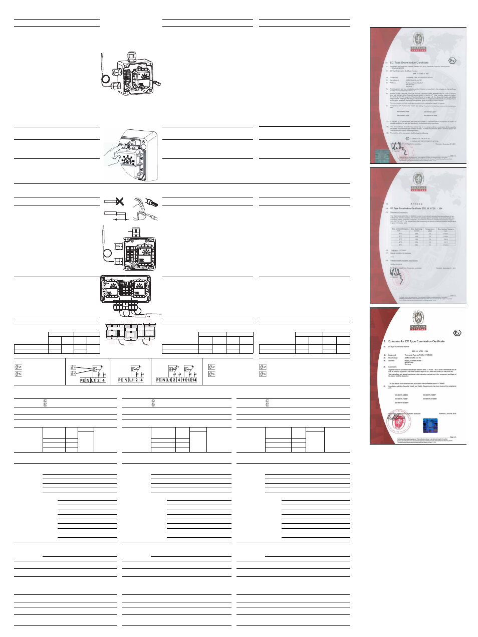
5.3 Anschlussbilder
= steigende Justage
= fallende Justage
TW / STW
STB
STB TW / STW
Wiring diagrams
= upward adjustment
= downward adjustment
Schémas de raccordement
= Etalonnage croissant
= Etalonnage décroissant
6. Technische Daten
Technical data
Caractéristiques techniques
ATEX-
Kennzeichnung
II 2G Ex d e IIC T4/T5/T6 Gb
II 2D Ex tb IIIC T85°C/T100°C/T130°C Db
ATEX mark
II 2G Ex d e IIC T4/T5/T6 Gb
II 2D Ex tb IIIC T85°C/T100°C/T130°C Db
Marquage ATEX
II 2G Ex d e IIC T4/T5/T6 Gb
II 2D Ex tb IIIC T85°C/T100°C/T130°C Db
IECEx-Kennzeich-
nung (optional)
Ex d e IIC T4/T5/T6 Gb
Ex tb IIIC T85°C/T100°C/T130°C Db
IECEx mark
(optional)
Ex d e IIC T4/T5/T6 Gb
Ex tb IIIC T85°C/T100°C/T130°C Db
Marquage IECEx
(optional)
Ex d e IIC T4/T5/T6 Gb
Ex tb IIIC T85°C/T100°C/T130°C Db
Prüfbescheinigung EPS 11 ATEX 1 354
Test certificate
EPS 11 ATEX 1 354
Certificat d’essai EPS 11 ATEX 1 354
Prüfbescheinigung
IECEx (optional)
IECEx EPS 13.0046
Test certificate
IECEx (optional)
IECEx EPS 13.0046
Certificat d’essai
IECEx (optional)
IECEx EPS 13.0046
zulässige Umge-
bungstempera-
tur im Gebrauch
Regelbereich mit
Skalenendwert
min. °C
max. °C
am
Temperaturfühler
max. Sollwert
+15 %
Admissible ambi-
ent temperature
in operation
Control range with
scale limit value
Min. °C
Max. °C
Max. setpoint
value on
the temperature
probe +15 %
Température am-
biante admissi-
ble en service
Plage de réglage
avec valeur fin
d’échelle
min. °C
max. °C
sur le capteur de
température
Consigne max.
+15%
siehe
Typen-
schild
See name-
plate
voir plaque
signalétique
< +200°C
-40 (-55)
< +200 °C
-40 (-55)
< +200°C
-40 (-55)
≥ 200 ≤ +350 °C
-40
≥ 200 ≤ +350 °C
-40
≥ 200 ≤ +350°C
-40
≥ 350 ≤ +500 °C -40 (-55)
≥ 350 ≤ +500 °C
-40 (-55)
≥ 350 ≤ +500°C
-40 (-55)
zulässige
Lagertemperatur max. +50 °C, min. -40 °C (-55 °C)
Admissible
storage
temperature
Max. +50 °C, min. -40 °C (-55 °C)
Température de
stockage
admissible
max. +50°C, min. -20°C (-55°C)
maximale
Schaltleistung
Am Öffnungskontakt (Kontaktbahn 1-2);
je nach Ausführung, siehe Typenschild
Maximum
switching
capacity
At N/C contact (contact deck 1-2);
depending on the version, see nameplate
Pouvoir de cou-
pure max.
Sur le contact à ouverture (contacts principaux 1-2);
suivant exécution, voir plaque signalétique
AC: 400 V +10 %, 16 A
AC: 400 V +10 %, 16 A
AC: 230 V +10%, 2 A
AC: 230 V +10 %, 16(2,5) A, cos
ϕ = 1(0,6)
AC: 230 V +10 %, 16(2.5) A, cos
ϕ = 1(0.6)
AC: 230 V +10%, 0,25 A
AC: 230 V +10 %, 25(4) A, cos
ϕ = 1(0,6)
AC: 230 V +10 %, 25(4) A, cos
ϕ = 1(0.6)
AC: 230 V +10%, 0,25 A
DC: 230 V +10 %, 0,25 A
DC: 230 V +10 %, 0.25 A
DC: 230 V +10%, 0,25 A
Am Schließkontakt (Kontaktbahn 1-4)
je nach Ausführung, siehe Typenschild
At N/O contact (contact deck 1-4);
depending on the version, see nameplate
Sur le contact à fermeture (contacts principaux 1-4)
suivant exécution, voir plaque signalétique
TW, STW
AC: 400 V +10 %, 6,3 A
TW, STW
AC: 400 V +10 %, 6.3 A
TW, STW
AC: 230 V +10%, 6,3 A
AC: 230 V +10 %, 6,3(2,5) A, cos j = 1(0,6)
AC: 230 V +10 %, 6.3(2.5) A, cos j = 1(0.6)
AC: 230 V +10%, 0,8 A
AC: 230 V +10 %, 2(0,4) A, cos j = 1(0,6)
AC: 230 V +10 %, 2(0.4) A, cos
ϕ = 1(0.6)
AC: 230 V +10%, 0,25 A
DC: 230 V +10 %, 0,25 A
DC: 230 V +10 %, 0.25 A
DC: 230 V +10%, 0,25 A
STB
AC: 400 V +10 %, 2 A
STB
AC: 400 V +10 %, 2 A
STB
AC: 230 V +10%, 2 A
AC: 230 V +10 %, 2(0,4) A, cos
ϕ = 1(0,6)
AC: 230 V +10 %, 2(0.4) A, cos
ϕ = 1(0.6)
AC: 230 V +10%, 0,3A
AC: 230 V +10 %, 2(0,4) A, cos
ϕ = 1(0,6)
AC: 230 V +10 %, 2(0.4) A, cos
ϕ = 1(0.6)
AC: 230 V +10%, 0,3A
DC: 230 V +10 %, 0,25 A
DC: 230 V +10 %, 0.25 A
DC: 230 V +10%, 0,25 A
Sprungschalter mit Goldauflage AC/DC 24V, 0,1 A
Gold-plated snap-action switch AC/DC 24 V, 0.1 A
Contact à rupture brusque avec revêtement doré AC/DC 24V, 0,1 A
minimale
Schaltleistung
Zur Gewährleistung einer möglichst großen Schaltsicherheit
empfehlen wir eine Mindestbelastung von:
AC / DC = 24V, 100 mA bei Silberkontakten
AC / DC = 10V, 5 mA bei vergoldeten Kontakten
Minimum
switching
capacity
To ensure that switching is as reliable as possible, we recommend
a minimum load of:
AC / DC = 24 V, 100 mA with silver contacts
AC / DC = 10 V, 5 mA with gold-plated contacts
Pouvoir de
coupure min.
Pour garantir la plus grande sécurité de coupure possible, nous vous
recommandons une charge minimale de :
AC / DC = 24V, 100 mA si contacts argentés
AC / DC = 10V, 5 mA si contacts dorés
Bemessungsstoßspannung: 2500 V
Rating surge voltage: 2500 V
Surtension transitoire de référence : 2500 V
erforderliche
Absicherung
siehe max. Schaltleistung
Required
fuse rating
See max. switching capacity
Fusible nécessaire
voir pouvoir de coupure max.
Schaltpunkt-
genauigkeit
bezogen auf den Sollwert
bei T
U
+22°C = siehe Typenschildangaben am Gerät.
Switching point
accuracy
Related to the setpoint
at TA +22 °C = see nameplate on device.
Précision du point
de contact
Par rapport à la consigne
pour T
U
+22°C = voir indication de la plaque signalétique
mittlerer Umge-
bungstemperatur-
einfluss bezogen auf
den Sollwert
Bei Abweichung der Umgebungstemperatur am Schaltkopf
und der Fernleitung von der Justierumgebungstemperatur
+22°C entsteht eine Schaltpunktverschiebung.
Höhere Umgebungstemperatur = niedriger Schaltpunkt;
Niedrigere Umgebungstemperatur = höherer Schaltpunkt.
Mean ambient tem-
perature influence
related to the set-
point
If the ambient temperatures at the switching head and the capilla-
ry deviate from the calibrated +22 °C ambient temperature, the
switching point is offset.
Higher ambient temperature = lower switching point;
lower ambient temperature = higher switching point.
Influence moyenne
de la température
ambiante
En cas de dérive de la température ambiante sur le boîtier et le capil-
laire +22°C, il en résulte un déplacement du point de contact.
Température ambiante plus élevée = point de contact plus bas ;
Température ambiante plus basse = point de contact plus haut.
Gewicht
ca. 1,2 kg Einfachthermostat, ca. 2,5 kg Doppelhermostat
Weight
Approx. 1.2 kg single thermostat, approx. 2.5 kg double ther-
mostat
Poids
env. 1,2 kg thermostat simple, env. 2,5 kg thermostat double
Schutzart
EN 60529 - IP66 (Polyestergehäuse), Verschmutzungsgrad 2
Protection type
EN 60529 - IP66 (polyester case), pollution level 2
Indice protection EN 60529 - IP66 (Boîtier polyester), degré de pollution 2
Betriebsmedium
Wasser, Öl, Luft, Heissdampf
Operating
medium
Water, oil, air, superheated steam
Milieu d’utilisa-
tion
eau, huile, air, vapeur
Zeitkonstante
t
0,632
in Wasser
in Öl
in Luft / Heissdampf
≤ 45 s
≤ 60 s
≤ 120 s
Time constant
t
0,632
In water
In oil
In air / superheated steam
≤ 45 s
≤ 60 s
≤ 120 s
Constante de
temps t
0,632
dans l’eau
dans l’huile
dans l’air/ vapeur surchauffée
≤ 45 s
≤ 60 s
≤ 120 s
11-13mm
( A )
( 2 )
(2)
( 1 )
( 1 )
( 1 )
( 1 )
(1.2)
(1.1)
(1.1)
(1.1)
(1.2)
(1.2)
ATEX-Zertifikate /
ATEX certificates / Certificats ATEX