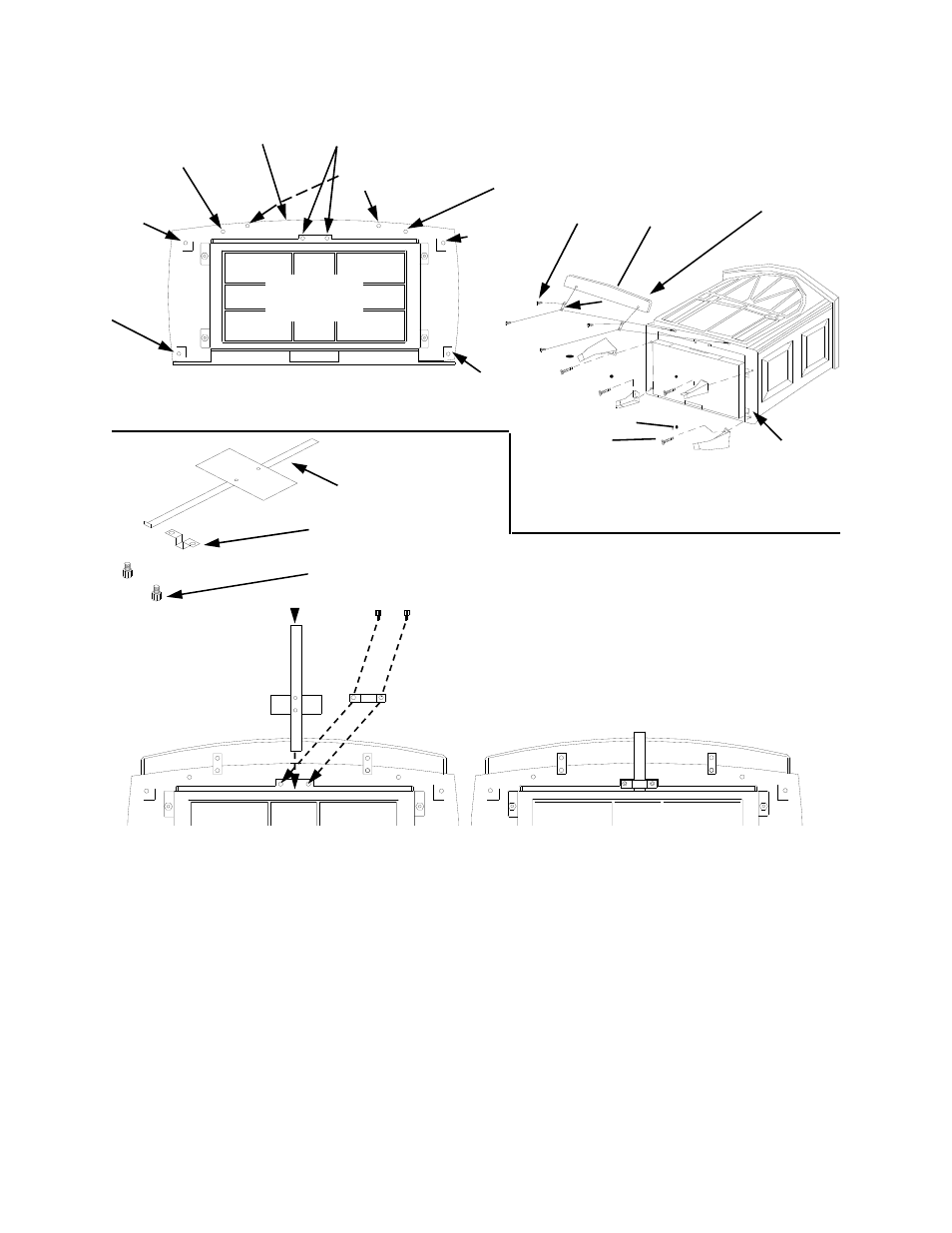
Figure 2, Figure 3: air control assembly installation – New Buck Corporation 21 User Manual
Page 9
BOTTOM
OF STOVE
UNIT
WASHERS
BOLTS
ATTACHING LEGS
FIGURE 2
7. Locate the Air Control assembly and hardware provided.
8. Follow the steps in figure 3 to install the Air Control assembly.
9. Attach the access cover door by inserting the step bolt through the door hinge pivot hole
(See Figure 4) and into the threaded hole (See Figure 4) in the bottom of the front of the
cast housing. Use an adjustable wrench or a 12 mm socket to fasten the step bolt. Tighten
the step bolt until snug. Make sure the door moves freely.
8. Next install the door catch bolt (M8 x 1.25-55 mm with two (2) M8 hex nuts) (see Figure 4)
into the threaded hole located on the front bottom of the cast housing (See Figures 2 and 4).
Use an adjustable wrench or a 12mm socket. The catch bolt has two (2) hex nuts attached to
it (See Figure 5). The top nut is a bolt stop and the bottom nut is for the door leveling ad-
justment.
9. Check general catch bolt alignment with door claw. Make final adjustment and door level-
ing after stove is in normal standing position.
PROTECTIVE
DROP BOTTOM
OF STOVE UNIT
LEG
HOLE
LEG
HOLE
DOOR CATCH BOLT
WITH ADJUSTABLE
HEX NUTS HOLE
FRONT
DOOR HINGE STEP-
BOLT HOLE
LEG
HOLE
LEG
HOLE
LOCATING THREADED HOLES FOR STOVE
BOTTOM COMPONENTS
BOLT HOLES FOR AIR CON-
TROL ROD HOLDER
HEARTH BRACKET
HOLES
HEARTH
HEARTH
BRACKETS
BOLTS
AIR CONTROL ASSEMBLY
AIR CONTROL ROD HOLDER
ALLEN HEAD BOLTS (2)
FIGURE 3: AIR CONTROL ASSEMBLY
INSTALLATION
STEP (1)
STEP (2)
STEP (3)
7