Wiring diagram: warning, Replacement parts – New Buck Corporation 21 User Manual
Page 24
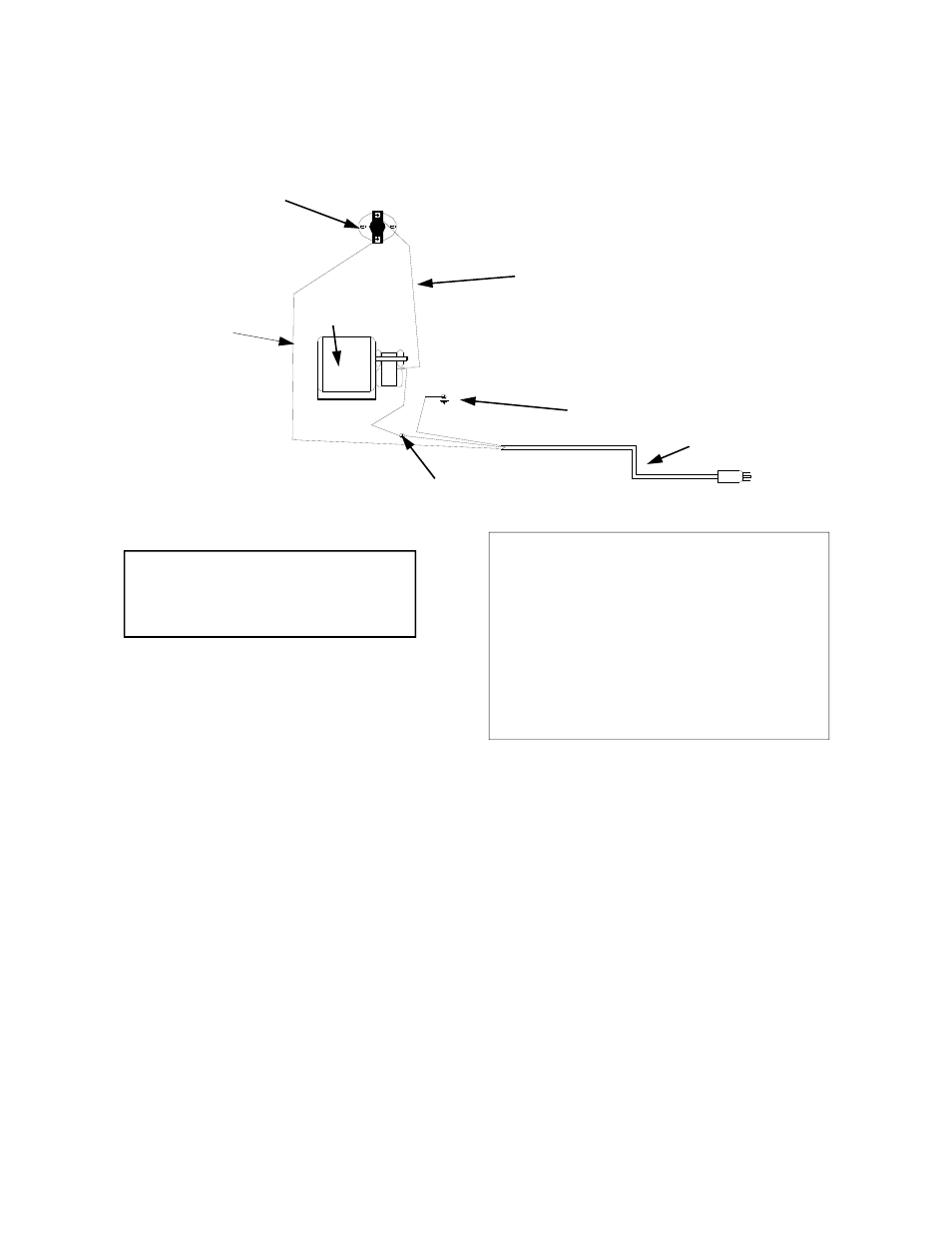
WIRING DIAGRAM:
WARNING:
ELECTRICAL GROUND-
ING INSTRUCTION: THIS APPLIANCE IS
EQUIPPED WITH A THREE-PRONG
(GROUNDING) PLUG FOR YOUR PROTEC-
TION AGAINST SHOCK HAZARD AND
SHOULD BE PLUGGED DIRECTLY INTO A
PROPERLY GROUNDED THREE-PRONG
RECEPTACLE. DO NOT CUT OR REMOVE
THE GROUNDING PRONG FROM THIS
PLUG.
NOTE: If any of the original wire as sup-
plied with the stove must be replaced, it
must be replaced with type 16 ga., 105 C.
rating wire or its equivalent.
GREEN WIRE (GROUND)
WHITE WIRE (TO MOTOR)
MOTOR TO THERMOSTAT
MOTOR
THERMOSTAT
POWER CORD
FROM POWER
SUPPLY TO THER-
MOSTAT
REPLACEMENT PARTS:
THERMOSTAT # PE 400132
BLOWER MOTOR #PE 42-40-01
POWER CORD # PE 400240
FOR ADDITIONAL PARTS CONTACT: NEW BUCK CORPORATION
P.O. BOX 69
SPRUCE PINE, NC 28777
(PHONE) 828-765-6144
22