New Buck Corporation 21 User Manual
Page 8
SECTION II
RESIDENTIAL FREESTANDING
INSTALLATION
PREPARING THE STOVE FOR INSTALLATION
The Model 21 Cast Iron Insert/Townsend III is made up of a steel firebox installed into a cast
iron outer housing. The assembly of these parts are completed by the manufacturer. The
following assembly steps must be completed by the installer.
1. Lift off corrugated box enclosing stove body crating. Remove plastic bag from stove body.
2. Inspect the unit for any obvious physical damage.
3. Open the firebox door and remove all contents from inside the firebox area (except the fire
brick). Contents include:
A. Legs with leg leveler bolts
B. Bottom access door with hardware
C. Top grates (3)
D. Door handle
E. Instruction Manual
F. Hearth with hardware
G. Air Control Assembly with hardware
H. Allen Wrench
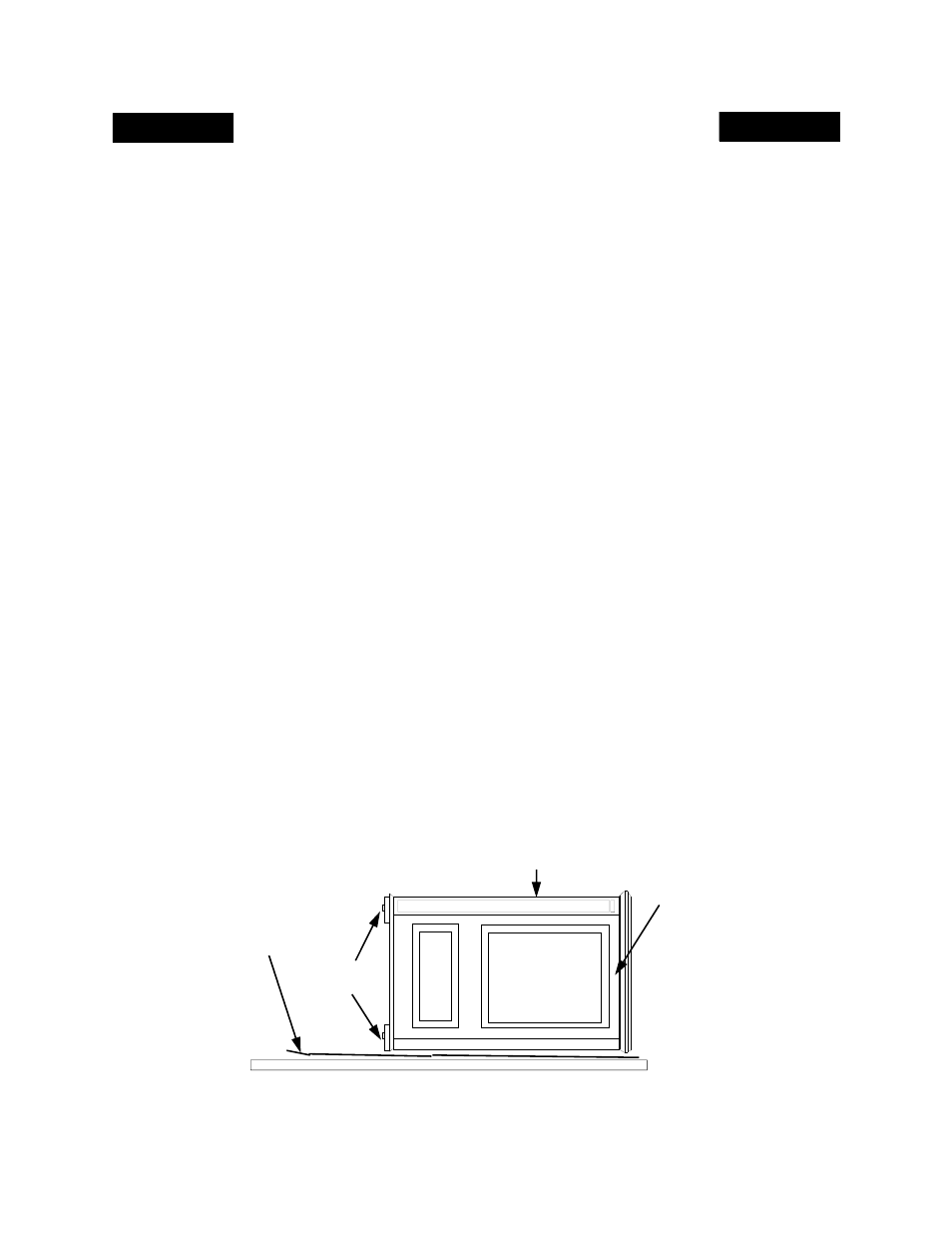
4. Spread a thick blanket on the floor behind the heater to protect the floor. Next, tilt the
heater so that the back is on the drop blanket (See Figure 1). NOTE: The heater is heavy
and may require two (2) people to lift.
5. Carefully lay the heater on its back and remove the pallet from the bottom of the heater (See
Figure 1) to attach the bottom components.
6. Fasten each leg with the four (4) M8 x 1.25-20 mm bolts provide. Use a flat washer with
each bolt. Tighten bolts into threaded holes on the cast stove (body) housing. Next attach
the hearth to the cast stove body using the (2) two brackets provided and the (4) bolts
provided (See Figure 2).
FIGURE 1 - LAYING DOWN STOVE ON SIDE
TOP OF
STOVE
UNIT
FRONT OF
STOVE UNIT
REMOVE PALLET
BOLTED TO
STOVE BOTTOM
BLANKET
6