Warning, Gas supply and piping, Gas supply requirements – Bryant 4-WAY MULTIPOISE 359AAV User Manual
Page 33: Gas piping requirements
33
1
″ (25.4mm) max.
Maintain 12
″ (304.8mm) clearance
above highest anticipated snow level
or grade whichever is greater.
Combustion
Air
Vent
25--22--02
12
″ (304.8mm) min.
Roof Overhang
A07736
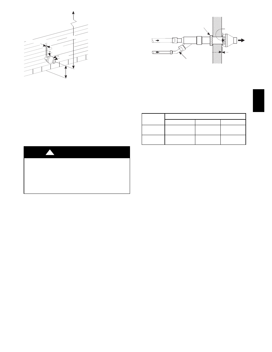
Fig. 34 -- Concentric Vent and Combustion--Air
Side Termination
9. Cement the furnace combustion air and vent pipes to the
concentric vent termination assembly. See Fig. 34 or Fig.
35 for proper pipe attachment.
10. Operate the furnace through one heat cycle to ensure com-
bustion air and vent pipes are properly connected to the
concentric termination connections.
GAS SUPPLY AND PIPING
FIRE AND EXPLOSION HAZARD
Failure to follow this warning could result in personal injury,
death, and/or property damage.
Models designated for Natural Gas are to be used with Natural
Gas ONLY, unless properly converted to use with Propane gas.
!
WARNING
NOTE: The rating plate is stamped with the model number, gas
type and gas input rating. In addition, models manufactured for
sale in Canada have orifice size information stamped on the
rating plate.
Gas Supply Requirements
Gas supply pressure should be within minimum and maximum
values listed on rating plate. Pressures are usually set by gas
suppliers.
(See Propane Gas Conversion Kit instruction manual for furnaces
converted to Propane gas)
S
Use only the Type of gas approved for this furnace. See rating
plate for approved gas type.
S
A
1
/
8
″ NPT plugged tapping, accessible for a test gauge
connection,must be installed immediately upstream of the gas
supply connection to furnace.
S
Gas supply pressure should be within minimum and maximum
values listed on rating plate. Pressures are usually set by gas
suppliers.
S
Gas input must not exceed the rated input shown on the rating
plate. Overfiring will result in failure of heat exchanger and
cause dangerous operation.
S
Do not allow minimum supply pressure to vary downward.
Doing so will decrease input to furnace. Refer to Table 5 for
Gas supply. Refer to Table 6 or 7 for manifold pressures.
Combustion
Air
Vent
Combustion
Air
Vent
45
° Elbow
(Field Supplied)
25--22--02
Strap
(Field Supplied)
Flush to
1
″ (25.4mm)
max.
Note:
Securing strap must be field installed to prevent movement of termina-
tion kit in side wall.
A07723
Fig. 35 -- Concentric Vent Sidewall Attachment
Table 5 – Gas Pressures
Gas Type
Supply Pressure
Recommended
Max.
Min.
Natural
7 in. w.c.
(1744 Pa)
14in. w.c.
(3487 Pa)
4.5in. w.c.
(1121 Pa)
Propane
11in. w.c.
(2740 Pa)
14in. w.c.
(3487 Pa)
11in. w.c.
(2740 Pa)
Gas Piping Requirements
NOTE: The gas supply line must be installed by a qualified
service technician in accordance with all building codes.
NOTE: In the state of Massachusetts.
a. Gas supply connections MUST be performed by a li-
censed plumber or gas fitter.
b. When flexible connectors are used, the maximum
length shall not exceed 36″(914 mm).
c. When lever handle type manual equipment shutoff
valves are used, they shall be T--handle valves.
d. The use of copper tubing for gas piping is NOT ap-
proved by the state of Massachusetts.
1. Install gas piping in accordance with local codes, or in the
absence of local codes, the applicable national codes. Re-
fer to the current edition of NFPA 54/ANSI Z223.1 for
proper gas pipe size.
2. It is recommended that a manual equipment shutoff valve
be installed in the gas supply line outside the furnace.
Locate valve as close to the furnace as possible where it is
readily accessible. Refer to Fig. 36 .
3. Use black iron or steel pipe and fittings or other pipe ap-
proved by local code.
4. Use pipe thread compound which is resistant to natural
and Propane gases.
5. Use ground joint unions and install a drip leg no less than
3″ long to trap dirt and moisture before it can enter gas
control valve inside furnace.
NOTE: Refer to Fig. 36 and Fig. 37 for the general layout at the
furnace. The rules listed apply to natural and Propane gas pipe
installations.
NOTE: Install the gas pipe grommet to the furnace side panel
with the gas pipe entry. If needed, remove the 2” (51 mm) hole
plug from the plastic accessory bag and relocate to the open hole
in the furnace side panel.
6. Use two pipe wrenches when making connections to pre-
vent gas valve from turning.
359AA
V