Installation, Vacuum connection, Power connection – INFICON VSA200 absolute switch User Manual
Page 2
Dimensions [mm]
DN 16 ISO-KF
101
.5
≈
60
10
ш30
ш26.5
34
4 VCR
female
4 VCR
male
24.
2
117
9
5.5
104
.5
117
.5
Weight
≈140 g
Installation
Vacuum Connection
DANGER
DANGER: overpressure in the vacuum system
>1 bar
Injury caused by released parts and harm
caused by escaping process gases can result if
clamps are opened while the vacuum system is
pressurized.
Do not open any clamps while the vacuum sys-
tem is pressurized. Use the type of clamps which
are suited to overpressure.
DANGER
DANGER: overpressure in the vacuum system
>2.5 bar
KF connections with elastomer seals (e.g.
O-rings) cannot withstand such pressures. Pro-
cess media can thus leak and possibly damage
your health.
Use O-rings provided with an outer centering
ring.
DANGER
DANGER: protective ground
Incorrectly grounded products can be extremely
hazardous in the event of a fault.
The gauge must be electrically connected to the
grounded vacuum chamber. This connection
must conform to the requirements of a protective
connection according to EN 61010:
• VCR
®
connections fulfill this requirement.
• For gauges with a KF connection, use a con-
ductive metallic clamping ring.
Caution
Caution: vacuum component
Dirt and damages impair the function of the vac-
uum component.
When handling vacuum components, take ap-
propriate measures to ensure cleanliness and
prevent damages.
Caution
Caution: dirt sensitive area
Touching the product or parts thereof with bare
hands increases the desorption rate.
Always wear clean, lint-free gloves and use
clean tools when working in this area.
Remove the protective lid and install the product to the vac-
uum system.
or
Seal with centering ring
Clamp
Seal with
centering ring
and filter
Protective lid
Keep the protective lid.
Power Connection
Make sure the vacuum connection is properly made
(
→ "Vacuum Connection").
Before connecting or disconnecting the product, turn
off the control system.
n
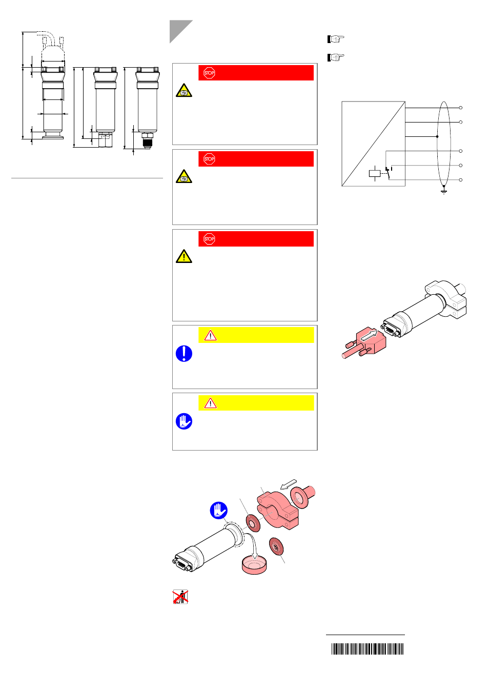
If no sensor cable is available, make one according to
the following diagram.
U
B
+
U
B
–
NC
NO
C
p
U
2
1
9
5
3
4
Pin 1 Supply common, GND
Pin 2 Supply +14V ... 30 V
Pin 3 Relay n.o.
Pin 4 Relay common
Pin 5 Relay n.c.
Pin 6 Internal common RxD
Pin 7 Internal common TxD
Pin 8 Internal common (com)
Pin 9 Housing (Chassis Ground)
o
Connect the cable to the vacuum switch.
t i na65e1
(2011-01)
Original: German tina65d1 (2011-01)