Adjustment and settings, Further information, Operation – INFICON BPG400 ATM to Ultra-High Vacuum Gauge User Manual
Page 4: Adjusting the gauge, Setting the switching functions
1
5
6
9
D-Sub, 9-pin,
male, soldering side
Pin 1
Setpoint A relay, N.O
1)
Pin 2
Do not connect
Pin 3
No connection
Pin 4
Do not connect
Pin 5
Setpoint A relay, N.C.
1)
Pin 6
RS485 (-) Input
2)
Pin 7
Setpoint A relay, COM
1)
Pin 8
No connection
Pin 9
RS485 (+) Input
2)
1)
The changeover relay contact available on the
RS485 interface connector is galvanically connected
to the N.O. relay contact of the setpoint A.
2)
In order to minimize cable reflections, the bus cable
must be terminated at both ends with appropriate
termination resistors.
o
Connect the RS485 cable to the gauge and secure the
RS485 cable connector using the lock screws.
The gauge can now be put into operation.
Operation
Caution
Caution: data transmission errors
If the gauge is operated via RS485 and RS232C
interface at the same time, data transmission
errors may occur.
The gauge must not be operated via RS485 and
RS232C interface at the same time.
Communication Protocol
The controlling host sends its commands to the individually
addressed devices (gauges) connected to the bus. In replay
the device returns the data requested via bus to the host.
A maximum of 127 devices can be connected to a RS485
bus system.
The device address (base address) setting is primarily made
on the gauge. Via RS485 communication, an address offset
can be added from the host:
Operating device
address
=
base address
+
Offset
where:
Operating device address
00 … 7F
hex
1)
Base address (Switches)
00 … 7F
hex
Offset (from host host)
00 … 7F
hex
1)
Sum of base address and offset must not exceed 7F
hex
.
The base address (0 … 127
dec
) is set in
hexadecimal form (00 … 7F
hex
) via the
"ADDRESS", "MSD", and "LSD" switches.
The address is polled by the firmware when
the gauge is switched on only. If the
address set by the switches is above the
allowed range, all parameters are set to the
factory default values. Communication is
not possible in this case.
Adjusting the Gauge
→ "Adjustment and settings".
Adjusting the Switching Functions
→ "Adjustment and settings".
On the BPG400-SR, lower and upper thresholds can
be set individually (only via the RS485), if certain
conditions are met (
→ [2]).
Adjustment and Settings
For BPG400-SD, BPG400-SP and BPG400-SR gauges.
Adjusting the Gauge
The gauge is factory calibrated. If used under different cli-
matic conditions, at extreme temperatures, through aging or
contamination and after exchanging the sensor, the charac-
teristic curve can be offset and readjustment can become
necessary. Only the Pirani element can be adjusted and only
at atmosphere.
Readjustment becomes necessary if
• at atmosphere the output voltage is <10 V or the display
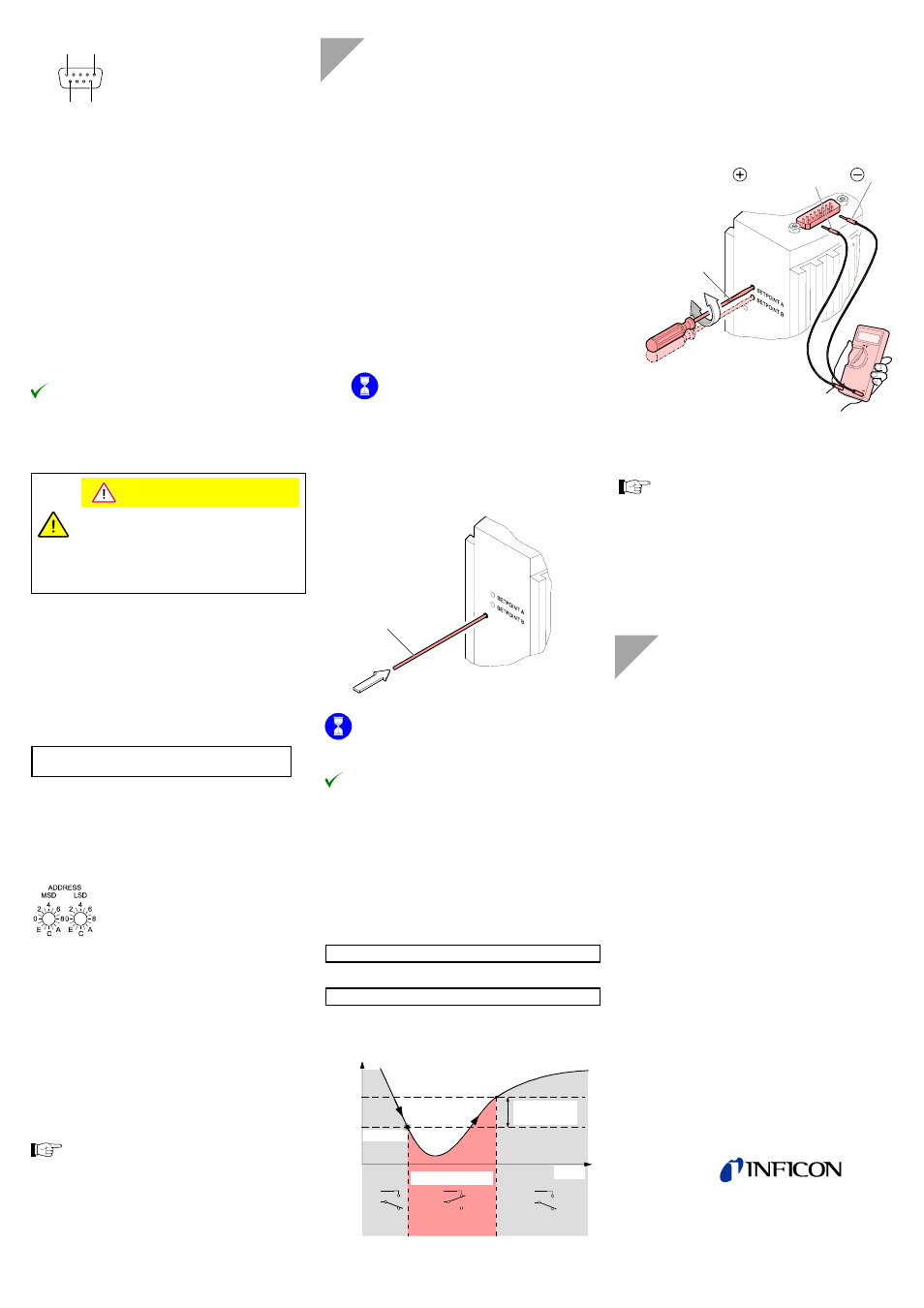
reading is • when venting the vacuum system, the output voltage reaches 10 V before the measured pressure has reached n If you are using a seal with centering ring and filter, → [1], [2], "Deinstallation"). o Activate the gauge. Operate the gauge for ≈10 minutes at atmos- pheric pressure. If the gauge was operated ≈30 minutes is to be expected (gauge p Adjusting the gauge: ≈ø1.3 mm) through the opening and push the button inside for at least 5 seconds. Max. ø1.3 The gauge is now automatically adjusted. The ≈4 s. The gauge is now adjusted. Setting the Switching Functions The threshold values of switching functions A and B can be -9 mbar … 100 mbar via potentiometers "SETPOINT A" and "SETPOINT B". For the Threshold , the following equation applies: For BPG400-SD, -SR: U Threshold = 0.75 × (log p Setpoint – c) + 7.75 For BPG400-SP: U Threshold = 0.8129401 × (log p Setpoint – c + 9.30102999) Constant c depends on the pressure unit ( → [1], [2]). Time t Mea sured value Off Off On Hysteresis Threshold Switching function Threshold U Measuring Signal (Pressure p) (Setpoint A, B) The hysteresis of the switching function is 10% of the thresh- n Put the gauge into operation. o Connect the +lead of a voltmeter to the threshold Max. ø2.5 Setpoint A Pin 3 Pin 5 p Using a screwdriver (max. ø2.5 mm), set the threshold Threshold . On the BPG400-SR, lower and upper thresholds can → [2]). A functional check of the switching functions (On/Off) is only → [3] for BPG400-SD, → [4] for BPG400-SP and (→ [2] for BPG400-SR) or → "Electrical Connection", sensor cable connector). Further Information [1] www.inficon.com [2] www.inficon.com [3] www.inficon.com [4] www.inficon.com [5] www.inficon.com [6] www.odva.org [7] www.profibus.com [8] European Standard for DeviceNet EN 50325 [9] European Standard for Profibus EN 50170 LI–9496 Balzers
atmosphere.
check that they are clean or replace them if necessary
(
within the Ioni range, a cooling-down time of
temperature = environmental temperature).
Insert a Pin (
adjustment takes
set within the pressure range 1×10
corresponding threshold voltages U
10% U
old setting.
measurement point of the selected switching function
("Setpoint A" Pin 3, "Setpoint B" Pin 6) and its –lead to
Pin 5.
Setpoint B Pin 6
of the selected switching function (Setpoint A, B) to the
desired value U
be set individually (only via RS485 interface,
possible via fieldbus interface (
by measuring the relay contacts with a continuity
checker/ohmmeter (
Instruction sheet
Bayard Alpert Pirani Gauge BPG400
tima03e1
INFICON AG, LI–9496 Balzers, Liechtenstein
Instruction manual
Bayard Alpert Pirani Gauge BPG400, BPG400-SD,
BPG400-SP, BPG400-SR
tina03e1
INFICON AG, LI–9496 Balzers, Liechtenstein
Communication protocol
DeviceNet™ BPG400-SD
tira03e1
INFICON AG, LI–9496 Balzers, Liechtenstein
Communication protocol
Profibus BPG400-SP
tira33d1
INFICON AG, LI–9496 Balzers, Liechtenstein
("Semiconductor and Vacuum coating processes,
Vacuum Gauges")
Product descriptions and downloads
INFICON AG, LI–9496 Balzers, Liechtenstein
Open DeviceNet Vendor Association, Inc.
"DeviceNet™ Specifications"
Profibus user organisation
Liechtenstein
Tel +423 / 388 3111
Fax +423 / 388 3700
[email protected]
www.inficon.com