Electrical connection, Operation – INFICON BPG400 ATM to Ultra-High Vacuum Gauge User Manual
Page 2
Sensor Cable Connection
For reasons of compatibility, the expression "sensor
cable" is used in this document, although the pres-
sure reading of the SD-type gauge is normally
transmitted via the DeviceNet interface.
Connector
D-Sub, 15 pins, male
Cable
Max. 15 conductors,
shielded
Cable length, (conductor cross
section per conductor)
≤35 m
(0.25 mm
2
)
≤50 m
(0.34 mm
2
)
≤100 m (1.0 mm
2
)
Switching functions
2
Setpoints adjustable via
potentiometers (Setpoints
A and B), one floating,
normally open contact per
setpoint
Relay contact rating
Voltage
Current
≤60 VDC
≤0.5 A
Gauge identification
42 k
Ω between Pin 10
(sensor cable) and GND
Grounding principle
→ "Electrical Connection"
Dimensions [mm]
Housing and vacuum connection
→ [1], [2]
Weight
353-507
353-508
≈430 g
≈695 g
Electrical Connection
Sensor Cable Connection
Make sure the vacuum connection is properly made
(
→ [1], [2], "Vacuum Connection").
n
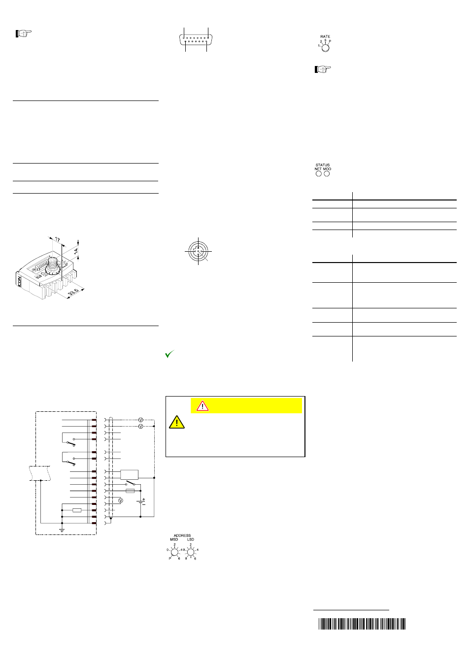
If no sensor cable is available, make one according to
the diagram.
SP A
SP B
SP A
SP B
TxD
RxD
Degas
+U
b
Measuring
signal
42 k
Ω
3
6
1
4
9
11
13
14
7
8
2
12
10
5
15
1.25 AT
24V
Degas
Identification
0V
RS232
1
8
9
15
D-Sub, 15 pins, female
soldering side
Pin 1
Relay switching function A, COM contact
Pin 2
Signal output (measuring signal) 0 … +10 V
Pin 3
Threshold (Setpoint) A
0 … +10 V
Pin 4
Relay switching function A, N.O. contact
Pin 5
Supply common GND
Pin 6
Threshold (Setpoint) B
0 … +10 V
Pin 7
Degas on, active high
+24 V
Pin 8
Supply of sensor electronics
+24 V
Pin 9
Relay switching function B, common
Pin 10
Gauge identification
Pin 11
Relay switching function B, N.O. contact
Pin 12
Signal common GND
Pin 13
RS232 TxD
Pin 14
RS232 RxD
Pin 15
Housing, shielding, GND
o
Connect the sensor cable to the gauge and secure it
using the lock screws:
DeviceNet Cable Connection
n
If no DeviceNet cable is available, make one according
to the following indications:
3
1
4
2
5
Micro-Style, 15 pins,
(DeviceNet), female
soldering side
Pin 1
Drain
Pin 2
Supply
+24 VDC
(DeviceNet interface only)
Pin 3
Supply common
GND
(DeviceNet interface only)
Pin 4
CAN_H
Pin 5
CAN_L
o
Connect the DeviceNet cable to the gauge and lock the
cable connector.
The gauge can now be put into operation.
Operation
Caution
Caution: data transmission errors
If the gauge is operated via an RS232 interface
and the DeviceNet at the same time, data trans-
mission errors may occur.
The gauge must not be operated via an RS232
interface and the DeviceNet at the same time.
Operating Software
Before the gauge is put into operation, it has to be configured
for the DeviceNet. A configuration tool and the device specific
EDS file (Electronic Data Sheet) are required for this pur-
pose. This software can be downloaded via internet
(
→ [5]).
Node Address Setting
Set the node address (0 … 63
dec
) via the
"ADDRESS" "MSD" and "LSD" switches.
The node address is polled by the firmware
when the gauge is switched on. If the set-
ting deviates from the stored value, the
new value is taken over into the NVRAM. If
a setting higher than 63 is made, the pre-
vious node address setting remains valid.
If the MSD switch is in the "P" position, the
node address is programmable via the
DeviceNet (
→ [3]).
Data Rate Setting
By means of the "RATE" switch, the data rate can
be set to 125 ("1"), 250 ("2") or 500 kBaud ("5").
If the switch is in any of the "P" positions, the data
rate is programmable via the DeviceNet (
→ [3]).
The admissible data rate depends on several factors
(system parameters, cable lengths etc.) (
→ [8]).
Adjusting the Gauge
→ Adjustment and settings.
Adjusting the Switching Functions
→ Adjustment and settings.
Status Lights
"STATUS MOD" (gauge status):
Light status
Meaning
Dark
No supply
Flashing
red/green
Selftest
Green
Normal operation
Red
Non recoverable error
"STATUS NET" (network status):
Light status
Meaning
Dark
Gauge not online:
– Selftest not yet concluded
– No supply,
→ "STATUS MOD" light
Flashing green
Gauge online but no connection:
– Selftest concluded, but no connection
to other nodes established
– Gauge not assigned to any master
Green
Gauge online; necessary connections
established
Flashing red
One or several input/output connections in
"timed out" status
Red
Communication error. The gauge has de-
tected an error that impedes communica-
tion via the network (e.g. two identical node
addresses (MAC ID) or "Bus-off")
t i ma 3 6 e 1 - b
(2004-02)
Original: German tima36d1-b (2004-02)