Adjustment and settings, Further information, Adjusting the gauge – INFICON BCG450-SP ATM to Ultra-High Vacuum Triple Gauge (Profibus) User Manual
Page 4: Setting the switching functions
Adjustment and Settings
For BCG450-SD and BCG450-SP gauges.
Adjusting the Gauge
The gauge is factory calibrated. If used under different cli-
matic conditions, at extreme temperatures, through aging or
contamination and after exchanging the sensor, the charac-
teristic curve can be offset and readjustment can become
necessary. However, this adjustment is carried out automati-
cally during operation by the gauge itself. No manual adjust-
ment is required (adjustment of the atmosphere sensor
→ [2]).
Setting the Switching Functions
The threshold values of switching functions A and B
1)
can be
set within the pressure range 1×10
-9
mbar … 100 mbar via
potentiometers "SETPOINT A" and "SETPOINT B". For the
corresponding threshold voltages U
Threshold
, the following
equation applies:
U
Threshold
= 0.75 × (log p
Setpoint
– c) + 7.75
Constant c depends on the pressure unit (
→ [1], [2]).
1)
Relays SP A/B can be reprogrammed for atmosphere
switching function via fieldbus interface (
→ [2]) (default
switching function A/B).
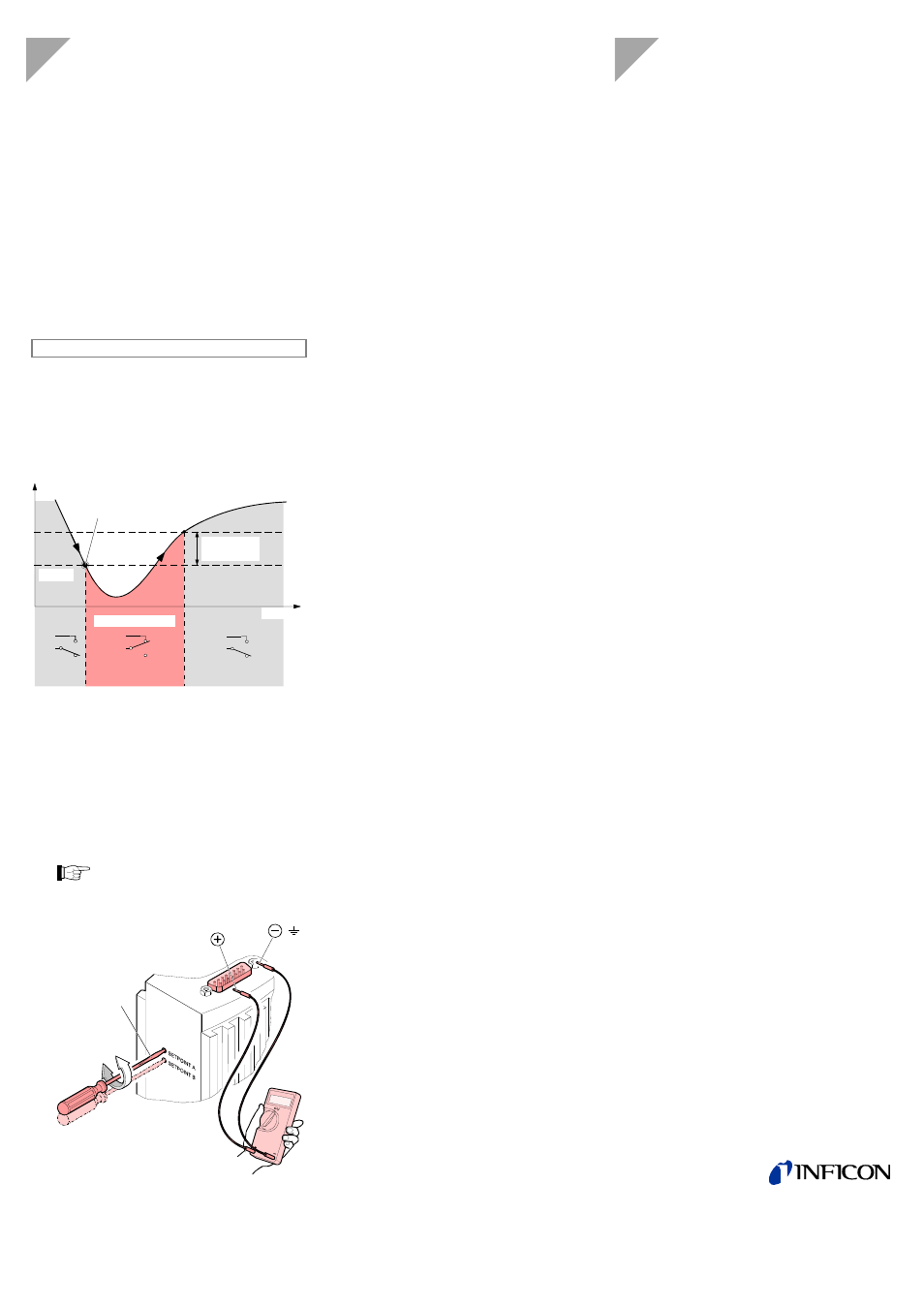
Time t
Mea
sured
value
Off
Off
On
Hysteresis
10% U
Threshold
Switching function
U
Threshold
Measuring signal
(Pressure p)
(Setpoint A, B)
The hysteresis of the switching function is 10% of the thresh-
old setting.
n
Put the gauge into operation.
o
Connect the + lead of a voltmeter to the threshold
measurement point of the selected switching function
("Setpoint A" Pin 3, "Setpoint B" Pin 6) and its – lead to
a ground contact nearby (eg. grounded locking screw
nut of connector or vacuum connection of the gauge).
The threshold voltages are referenced to
ground (housing, vacuum connection), not to
Pin 5 (common power GND 24 V supply).
max. ø2.5
Setpoint A Pin 3
Setpoint B Pin 6
( )
p
Using a screwdriver (max. ø2.5 mm), set the threshold
of the selected switching function (Setpoint A, B) to the
desired value U
Threshold
.
A functional check of the switching functions (On/Off) is only
possible via fieldbus interface (
→ [3] for BCG450-SD,
→ [4] for BCG450-SP) or by measuring the relay contacts
with a continuity checker/ohmmeter (
→ "Electrical Connec-
tion", sensor cable connector).
Further Information
[1] www.inficon.com
Instruction sheet
TripleGauge™ BCG450
tima40d1 German
tima40e1 English
INFICON AG, LI–9496 Balzers, Liechtenstein
[2] www.inficon.com
Instruction manual
TripleGauge™ BCG450, BCG450-SD, BCG450-SP
tina40d1 German
tina40e1 English
INFICON AG, LI–9496 Balzers, Liechtenstein
[3] www.inficon.com
Communication protocol
DeviceNet™ BCG450-SD
tira40e1 English
INFICON AG, LI–9496 Balzers, Liechtenstein
[4] www.inficon.com
Communication protocol
Profibus BCG450-SP
tira41d1 German
tira41e1 English
INFICON AG, LI–9496 Balzers, Liechtenstein
[5] www.inficon.com
("Semiconductor and Vacuum coating processes,
Vacuum Gauges")
Product descriptions and downloads
INFICON AG, LI–9496 Balzers, Liechtenstein
[6] www.odva.org
Open DeviceNet Vendor Association, Inc.
"DeviceNet™ Specifications"
[7] www.profibus.com
Profibus user organisation
[8] European Standard for DeviceNet EN 50325
[9] European Standard for Profibus EN 50170
LI–9496 Balzers
Liechtenstein
Tel +423
/
388
3111
Fax +423 / 388 3700
[email protected]
www.inficon.com