Bcg450-sp, General information, Technical data bcg450-sp – INFICON BCG450-SP ATM to Ultra-High Vacuum Triple Gauge (Profibus) User Manual
Page 3: Power connection, Operation
BCG450-SP
General Information
The BCG450-SP gauge has a fieldbus interface
that conforms to the Profibus DPV1 standard
(
→ [9]).
Via this interface, the following and further data
are exchanged in the standardized Profibus proto-
col (
→ [1], [2]):
• Pressure reading
• Pressure unit (mbar, Torr, Pa)
• Degas function
• Status and error messages
Two adjustable switching functions are integrated in the
gauge. With the built-in atmosphere switching function an
atmospheric pressure thresold can be programmed
(
→ [2]). The corresponding relay contacts are available at
the sensor cable connector.
The basic sensor and sensor electronics of the BCG450-SP
type are the same as in the standard BCG450 (
→ [1], [2]).
Technical Data BCG450-SP
General technical data of the sensor and sensor
electronics
→ [1], [2].
Fieldbus Interface
Fieldbus name
Profibus
Standard applied
→ [9]
Communication protocol,
data format
→ [4], [9]
Interface, physical
RS485
Profibus Parameters
Data rate
≤12 Mbaud (
→ [4], [9])
Node address
00 … 7D
hex
(0 … 125
dec
)
(default 5C
hex
)
Profibus connection
D-Sub, 9-pin, female
Cable
Shielded special Profibus
cable (
→ [7], [9])
Cable length, system wiring
According to Profibus
specifications
(
→ [7], [9])
Supply Voltages
Supply voltage at sensor cable
connector, Pin 8
+24 VDC (+20 … +28 V)
Power consumption
<20 W
Sensor Cable Connection
For reasons of compatibility, the expression "sensor
cable" is used in this document, although the pres-
sure reading of the SD-type gauge is normally
transmitted via the DeviceNet interface.
Connector
D-Sub, 15-pin, male
Cable Max.
15
conductors,
shielded
Cable length, (conductor cross
section per conductor)
≤35 m (0.25 mm
2
)
≤50 m (0.34 mm
2
)
≤100 m (1.0 mm
2
)
Switching functions
2
Setpoints adjustable via
potentiometers (Setpoints
A and B), one floating,
normally open contact per
setpoint
Relay contact rating
≤60 VDC, ≤0.5 ADC
Atmosphere switching function
→ [2]
Gauge identification
42 k
Ω between Pin 10
and Pin 5 (sensor cable)
Grounding principle
→ "Power Connection"
Dimensions
Housing and vacuum connection
→ [1], [2]
Weight
353-554
353-556
≈445 g
≈710 g
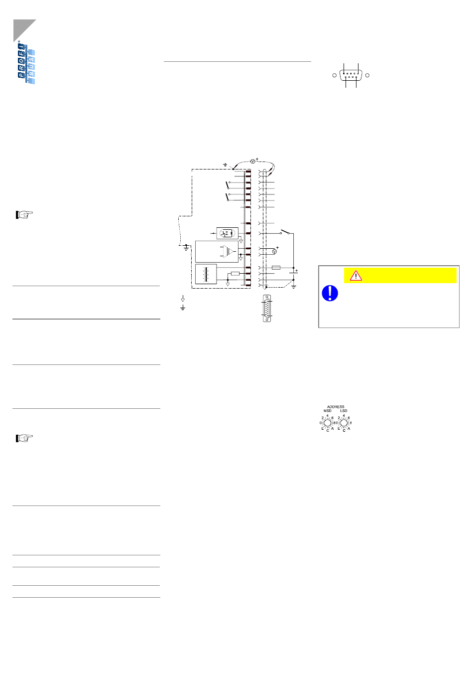
Power Connection
Sensor Cable Connection
Make sure the vacuum connection is properly made
(
→ [1], [2], "Vacuum Connection").
n
If no sensor cable is available, make one according to
the diagram.
Common (power GND 24V supply)
Ground (housing, vacuum connection)
SP A
SP B
SP A
2)
SP B
2)
Degas
42 k
Ω
3
6
1
4
9
11
13
14
7
8
2
12
5
15
1.25 AT
24V
Degas
Ident.
10
-
Threshold values
-
-
1)
( )
+
-
Measuring
signal
-
D-Sub,15-pin,
female,
soldering side
8
9
1
15
Electrical Connection
Pin 1
Relay switching function A, n.o. contact
2)
Pin 2
Measuring signal output
0 … +10.13 V
Pin 3
Threshold (setpoint) A
1)
0 … +10 V
Pin 4
Relay switching function A, com contact
2)
Pin 5
Supply common
0 V
Pin 6
Threshold (setpoint) B
1)
0 … +10 V
Pin 7
Degas on, active high
0 V/+24 V
Pin 8
Supply +24
V
Pin 9
Relay switching function B, n.o. contact
2)
Pin 10
Gauge identification
Pin 11
Relay switching function B, com contact
2)
Pin 12
Measuring signal common
Pin 13
Do not connect
Pin 14
Do not connect
Pin 15
Do not connect
1)
Do not connect pin 3 and pin 6 for normal operation
of the gauge. These pins are reserved for adjust-
ment of the setpoint potentiometers (
→ "Setting the
Switching Functions").
2)
Reprogrammable for atmosphere switching function
via fieldbus interface (
→ [2]).
o
Connect the sensor cable to the gauge and secure the
sensor cable connector using the lock screws.
Profibus Cable Connection
n
If no Profibus cable is available, make one according to
the following indications:
1
5
6
9
D-Sub, 9-pin, male
soldering side
Pin 1
do not connect
Pin 2
do not connect
Pin 3
RxD/TxD-P
Pin 4
CNTR-P
1)
Pin 5
DGND
2)
Pin 6
VP
2)
Pin 7
not connected internally
Pin 8
RxD/TxD-N
Pin 9
not connected internally
1)
Only to be connected if an optical link module is
used.
2)
Only required as line termination for devices at both
ends of bus cable (
→ [9]).
o
Connect the Profibus cable to the gauge and secure
the Profibus cable connector using the lock screws.
Operation
Caution
Caution: data transmission errors
The attempt to operate the BPG450-SP with the
RS232C interface causes data transmission
errors.
The BPG450-SD must not be operated with the
RS232C interface.
Operating Software
For operating the gauge via the Profibus network, prior in-
stallation of the gauge specific GSD file is required. This
software can be downloaded via internet (
→ [5]).
Note Address Setting
The node address (0 … 125
dec
) is set in
hexadecimal form (00 … 7D
hex
) via the
"ADDRESS", "MSD", and "LSD" switches
(default 5C
hex
). The node address is polled
by the firmware when the gauge is
switched on. If the setting deviates from the
stored value, the new value is taken over
into the NVRAM. If a value >125
dec
(>7D
hex
)
is entered, the node address setting
currently stored in the device remains valid
but it can now be defined via Profibus ("Set
slave Address",
→ [4]).
Adjusting the Gauge
Gauge adjustment is carried out automatically, no manual
adjustment is required required (adjustment of the
atmosphere sensor
→ [2]).
Adjusting the Switching Functions
→ "Adjustment and settings".