Butt contact pushbutton switches series 30 and 46, Decorator line features, Circuitry dimensions – Grayhill Pushbutton switches: Butt Contact 46 Series User Manual
Page 2: Recommended panel cutout and mounting hardware, Dpdt–break before make
Pushbutton Switches
Grayhill, Inc. • 561 Hillgrove Avenue • LaGrange, Illinois 60525-5997 • USA • Phone: 708-354-1040 • Fax: 708-354-2820 • www.grayhill.com
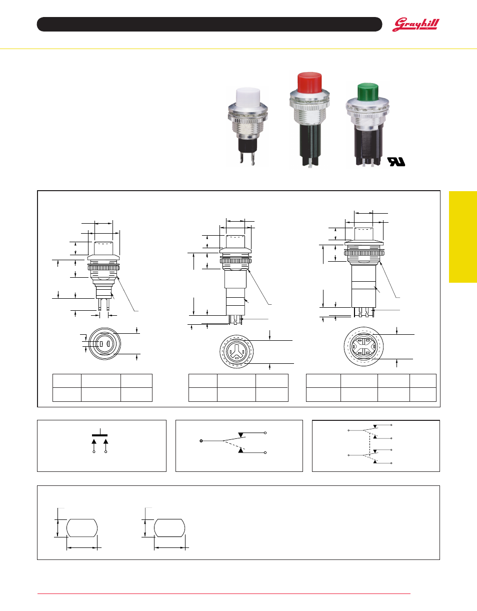
Butt Contact Pushbutton Switches
SerieS 30 and 46
decorator Line
FeatureS
• Attractive Front Panel Bezels (6 choices)
• Space-Saving: Only 5/8" Diameter
(SPST & SPDT) and 3/4" Diameter (DPDT)
Round Bezels
• SPST with Option of Positive Feel
• SPDT, DPDT with Momentary Contact or
Alternate Action
• Sturdy Metal Sleeve or Bushing and Nut
Provide Secure Mounting
• UL Recognized Version
SPdt–Break Before Make
SPSt–normally Open
Partial
Part no.
Feature
dim.
F
dim.
a
Momentary 46-05-05-502-*
.992 (25,20)
Alt. Action
46-05-07-502-* 1.278 (32,46)
Partial
Part no.
Feature
dim.
a
Momentary 30-05-01-502-*
.710 (18,03)
Pos. Feel
30-05-04-502-*
.910 (23,11)
Partial
Part no.
Feature
dim.
a
46-05-05-502-*
46-05-07-502-*
30-05-01-502-*
30-05-04-502-*
CirCuitry
diMenSiOnS
in inches (and millimeters)
*Partial part number; complete part number by adding a dash for button color: white -01; red -03;
green -04; blue -05; yellow -06 or black -07, see Ordering Information.
** Contact Grayhill for part number.
Mounting Hardware
For 46-05-08-502 & 46-05-09-502:
One internal tooth lockwasher
One knurled ring nut .765 ± .010 (19,43 ± 0,25) Dia.
.094 ± .010 (2,39 ± 0,25) Thk.
For SPSt & SPdt switches
One internal tooth lockwasher
One knurled ring nut .640 ± .010 (16,26 ± 0,25) Dia.
.094 ± .010 (2,39 ± 0,25) Thk.
reCOMMended PaneL CutOut and MOuntinG HardWare
Note: All switches fit panels up
to .250 (6,35) thick, except 46-
05-08-502 which fits panels up
to .187 (4,75) thick.
Front and back panel access
required for installation.
.440 (11,17) MIN.
ACROSS FLATS
.516 (13,10)
MIN. DIA.
.565 (14,35) MIN.
ACROSS FLATS
.641 (16,28)
MIN. DIA.
SPSt and SPdt VerSiOn dPdt VerSiOn
Momentary
46-05-08-502-* 1.001 (25,43) .314 (7,98)
Alt. Action
46-05-09-502-* 1.130 (28,70) .355 (9,02)
Terminals are marked on switch.
Terminals are marked on switch.
dPdt–Break Before Make
46-05-08-502-* (UL)**
46-05-09-502-*
.555 – .005
(14,10 – 0,13)
ACROSS FLATS
5/8-32 UN-2A
THREAD
INSULATING
BARRIER
B = .375 – .010
(9,35 – 0,25)
DIA.
C = .750 – .005
(19,05 – 0,13)
DIA.
D = .255 – .032
(6,48 – 0,81)
F = SEE CHART
– .015 (0,38)
E = .093 – .010
(2,36 – 0,25)
G = .150 – .010
(3,81 – 0,25)
DIM A
– .015
(0,38)
(SEE CHART)
F
D
E
G
.187 – .015
(4,75 – 0,38)
NO
NO
C
CN
C
NC
B
C
LABEL*
*PART NUMBER
AND E.I.A. DATE
CODE LABEL
.100 ± .005
(2,54 ± 0,13)
.430 ± .005
(10,92 ± 0,13)
ACROSS FLATS
1/2-32 UN-2A
THREAD
B = .375 ± .010
(9,53 ± 0,25)
DIA.
C = .625 ± .005
(15,88 ± 0,13)
DIA.
D = .255 ± .032
(6,48 ± 0,81)
E = .093 ± .010
(2,36 ± 0,25)
F = .355 ± .015
(9,02 ± 0,38)
G = .220 ± .025
(5,59 ± 0,64)
DIM A
± .020
(0,51)
(SEE CHART)
F
G
D
E
C
B
LABEL*
*PART NUMBER
AND E.I.A. DATE
CODE LABEL
.186
(4,72)
REF.
C
L C
L
SPSt n.O.
SPdt - BBM
n.C.
n.O.
C.
dPdt BBM
n.C.
n.O.
C1
n.C.
n.O.
C2
NC
NO
C
.430 – .005
(10,92 – 0,13)
ACROSS FLATS
1/2-32 UN-2A
THREAD
B = .375 – .010
(9,53 – 0,25)
DIA.
C = .625 – .005
(15,88 – 0,13)
DIA.
D = .255 – .032
(6,48 – 0,81)
E = .093 – .010
(2,36 – 0,25)
F = .355 – .015
(9,02 – 0,38)
G = .150 – .010
(3,81 – 0,25)
DIM A
– .015
(0,38)
(SEE CHART)
F
D
E
G
.187 – .015
(4,75 – 0,38)
INSULATING
BARRIER
B
C
LABEL*
*PART NUMBER
AND E.I.A. DATE
CODE LABEL