Bearing for door or window header, Bearing at concrete wall – Georgia-Pacific GP Lam LVL User Manual
Page 8
LvL allowable Holes
double I-Joists
LvL Storage, Handling, and Installation
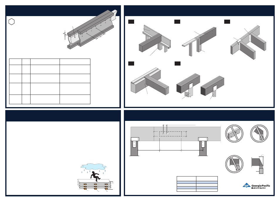
bearing details
beam-to-beam Connection
bearing at wall
bearing at wood or Steel Column
Side plates are required for lateral restraint (if at
beam ends) and side plate connections may be
required for lateral load transfer.
bearing for door or
window Header
bearing area is extremely
critical and must be considered
for each application.
Multiple plies of GP Lam
®
LVL can be fastened
together to form a beam or header of the
required size, up to a maximum width of 7(
for 1
3
⁄
4
( and 3
1
⁄
2
( thick plies.
Engineered wood
rim blocking
(as shown) or
rim board
Built-up wood column
bearing at Concrete wall
Protect GP Lam
®
LVL from direct
contact with concrete or masonry per
local code requirements
Strap per code if top
plate is not continuous
over headers
Trimmers (see minimum
bearing lengths from
uniform load tables in
the Product Guide or
from software analysis)
Top-mount
hanger
Face-mount hanger
Wood column
with column cap
Steel column with
column cap
B1
B4
B5
B2
B3
2 x diameter of the largest hole (minimum)
Allowable Hole Zone
1
⁄
3
depth
1
⁄
3
depth
1
⁄
3
depth
1
⁄
3
span
1
⁄
3
span
1
⁄
3
span
Allowable Hole Zone
GENERAL NOTES
• The Allowable Hole Zone is suitable for uniformly
loaded beams using maximum loads for any
tables in the LVL User’s Guide. For other load
conditions or hole configurations, please contact
your GP Lam LVL representative.
• If more than one hole is to be cut in the beam,
the length of the uncut beam between holes
must be a minimum of twice the diameter of
the largest hole. No more than three holes are
allowed per span.
• Rectangular holes are not allowed.
• Holes in cantilevers require additional analysis.
• Required hole clearance and the effects of
beam deflection must be considered to prevent
problems with utilities that penetrate the holes.
• Maximum hole diameter is:
Do not cut, notch or drill
holes in GP Lam LVL except
as indicated in illustration for
allowable holes
Do not overhang seat cuts
on GP Lam LVL beams
from inside face of support
member
Confirm the required bearing area is provided by a
support that has adequate strength to carry the load.
Beam Depth
Maximum Round Hole
Diameter
3
1
⁄
2
(-7(
3
⁄
4
(
7
1
⁄
4
(-9
1
⁄
4
(
1
1
⁄
2
(
9
1
⁄
2
(-16(
2(
Deeper than 16(
3(
• GP Lam LVL should be stored and handled lying flat and
protected from the weather (sun and precipitation). Keep
covered until installed.
• Keep the LVL above ground to minimize the absorption of
ground moisture and allow air circulation.
• Re-cover unused products with bundle wrap. Repair
damage to bundle wrap with tape, more bundle wrap,
plastic or weatherproof covering.
• GP Lam LVL is only to be used in covered, dry use conditions
only (moisture content less than 16%). When in contact with
concrete or masonry, protect LVL per code.
• GP Lam LVL is produced without camber so either edge can
be used as the top (edgewise orientation).
• Nails installed in the narrow face of the LVL must be spaced
no closer than 3( (8d), 4( (10-12d, 16d sinker) and 8( (16d).
• Do not ship or install any damaged LVL.
• Deeper LVL depths have a greater potential for cupping and
damage from improper storage and handling.
• Except for cutting to length, LVL shall not be cut, drilled or
notched, except as shown in the design guide. Heel cuts
may be possible. Contact your GP Lam representative.
• 1
3
⁄
4
( plies that are deeper than 14( require multiple plies, or
must be full-depth blocked or full-depth restrained on both
sides of the ply at intervals not exceeding 24( o.c.
• Lateral support of LVL compression edge is required at
intervals not exceeding 24( o.c and at bearing locations.
• Do not splice LVL like dimension lumber. LVL ends must butt
over a support that provides the bearing required at each
end of the LVL.
• Fasteners, hangers or connectors for LVL framing either
from or into preservative or fire-retardant treated wood
must be hot-dip galvanized, or stainless steel, as required
by code and the type of treatment.
• Treating GP Lam LVL is not recommended, voids the
warranty and could present a safety and performance
concern.
CAUTION:
Wrap and LVL
may be slippery
when icy or wet
You’re purchasing a premium Georgia-Pacific product–protect your investment! Proper product care minimizes problems. Failure
to follow good procedures for storage, handling and installation could result in unsatisfactory performance and unsafe structures.
When handling Georgia-Pacific products use personal protective equipment for eyes, hands and feet.
Align stickers one
above the other
Hard, dry,
level surface
8*-0(
max.
10*-0(
max.
Do not
bevel-cut
beam
past
inside
face of
support
Inside
face
of support
Do not notch underside of
beam at bearing location
Georgia-Pacific, Wood I Beam, GP Lam and Fiberstrong are trademarks owned by or licensed to Georgia-Pacific Wood Products LLC. APA Rated, Sturd-I-Floor, APA Rim Board and APA Rim Board Plus are registered trademarks of APA-The Engineered Wood Association.
©2012 Georgia-Pacific Wood Products LLC. All rights reserved. GP-TM 8/12 Lit. Item #621579.
Joist
Joist
Regular Filler Blocking
Full-Depth Filler Blocking
Series
Depth
Use in detail F12
Use in details C4, F13, F14 & R7
9
1
⁄
2
9
2x6 2x6
11
7
⁄
8
9 2x6
2x8
149
2x8 2x10
9
1
⁄
2
9
2x6 +
3
⁄
8
9 OSB/Plywood
2x6 +
3
⁄
8
9 OSB/Plywood
11
7
⁄
8
9
2x6 +
3
⁄
8
9 OSB/Plywood
2x8 +
3
⁄
8
9 OSB/Plywood
149
2x8 +
3
⁄
8
9 OSB/Plywood
2x10 +
3
⁄
8
9 OSB/Plywood
9
1
⁄
2
9
2x6 +
5
⁄
8
9 OSB/Plywood
2x6 +
5
⁄
8
9 OSB/Plywood
11
7
⁄
8
9
2x6 +
5
⁄
8
9 OSB/Plywood
2x8 +
5
⁄
8
9 OSB/Plywood
149
2x8 +
5
⁄
8
9 OSB/Plywood
2x10 +
5
⁄
8
9 OSB/Plywood
169
2x8 +
5
⁄
8
9 OSB/Plywood
2x12 +
5
⁄
8
9 OSB/Plywood
11
7
⁄
8
9
(2) 2x6
(2) 2x8
149
(2) 2x8
(2) 2x10
169
(2) 2x8
(2) 2x12
GPI 20
GPI 40
GPI 65
WI 40
WI 60
GPI 90
WI 80
Filler blocking
1/89 gap
DOUBLE JOIST CONSTRUCTION
WITH FILLER
Note: Filler blocks and
fastening between joists
can be omitted when double
joists are loaded evenly
from above to the tops of
both joists, such as when a
parallel bearing wall is
directly centered over the
double joist.
1. Support back of web during nailing to prevent damage
to web-flange connection.
2. Leave
1
⁄
8
9 gap between top of filler blocking and bottom
of top flange.
3. Block solid between joists. For all applications except
cantilever reinforcement, filler need not be one continuous
length, but must extend the entire length of span. For double
I-joist cantilever reinforcement C4, filler must be one
continuous pieceextending the full length of the reinforcement.
4. Place joists together and nail from each side with 2 rows of 10d (16d for WI 80 and GPI 90)
nails at 129 o.c., clinched when possible. Stagger rows from opposite sides by 69.
F11
Installation Guide