Web stiffeners allowable floor spans, Bearing stiffeners, Load stiffeners – Georgia-Pacific GP Lam LVL User Manual
Page 2
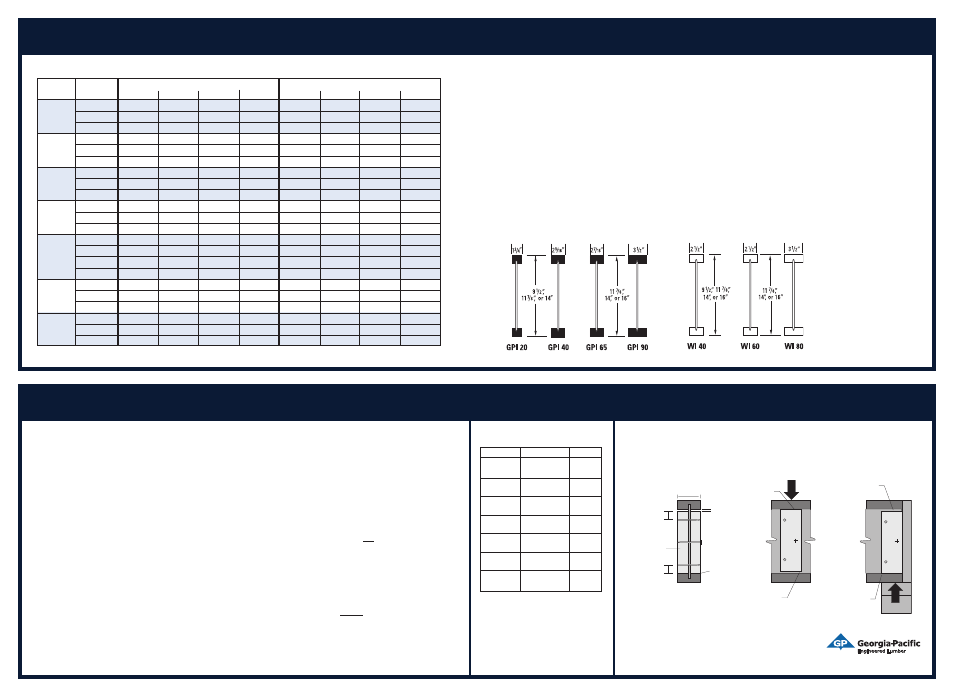
web Stiffeners
allowable floor Spans
GP Joist web Stiffener requirements
web stIffener sizes
Web stiffeners are not required to attain the spans shown in this guide, but are required for conditions as described in this
section. There are two main types of web stiffeners: bearing stiffeners and “load” stiffeners. Although both types reinforce
the I-joist at locations of concentrated loads, the bearing stiffeners are located at bearing points and may also be required for
hangers with side or angle nailing, or to provide lateral restraint to the I-joist in some hanger applications and at birdsmouth
cuts. The load stiffeners are located away from bearing supports anywhere large point loads are applied to the top flange of
the I-joist.
bearInG StIffenerS:
1. Bearing stiffeners are required:
• When sides of the hangers or adjacent framing do not laterally brace the top flange of each I-joist.
• For all I-joists that have a design end reaction exceeding 1550 lbs (1900 lbs for GPI 90).
2. Install bearing stiffeners tight against the bottom flange of the I-joist, leaving 1/8”–1/4” gap at the top.
Load StIffenerS:
3. Load stiffeners are required:
• When I-joists are designed to support concentrated loads that exceed 1500 lbs applied to the top flange between supports.
• For concentrated loads on cantilevers that exceed 1500 lbs, but do not exceed the un-reinforced I-joist shear capacity, load
stiffeners are required. If the full loading on the cantilever exceeds the shear capacity of the un-reinforced joist, cantilever
reinforcement is required per the instructions in this guide.
4. Install load stiffeners tight against the top flange of the I-joist, leaving 1/8”–1/4” gap at the bottom.
5. The minimum bearing length for concentrated loads is 3½”.
6. Except for pre-scored knock-outs, concentrated loads must be applied with 6” minimum horizontal distance between the
edge of the load and the edge of the web hole.
Web stiffeners may be supplied by the distributor, or may be cut in the field as required.
CONCENTRATED LOAD
(Load Stiffeners)
END BEARING
(Bearing Stiffeners)
Flange width
greater than 1
3
⁄
4
”
±2”
±2”
1
⁄
8
”-
1
⁄
4
” Gap
No Gap
Tight Joint
No Gap
1
⁄
8
”-
1
⁄
4
” Gap
1
⁄
8
”-
1
⁄
4
” Gap
Tight Joint
No Gap
(Bearing Stiffener Case Shown)
Installation Guide
40 PSf Live Load + 20 PSf dead Load; Improved Performance (L/480)
Joist
Joist
Spacing (Simple Span)
Spacing (Multiple Span)
Series
Depth
129 o.c.
169 o.c.
19.29 o.c.
249 o.c.
129 o.c.
169 o.c.
19.29 o.c.
249 o.c.
9
1
⁄
2
9 17’-019 15’-079 14’-099 13’-109 18’-079 17’-009 15’-079 13’-119
GPI 20
11
7
⁄
8
9 20’-059 18’-089 17’-089 15’-119 22’-039 19’-059 17’-099 15’-059
149 23’-039 21’-039 19’-069 17’-059 24’-089 21’-049 19’-039 15’-059
9
1
⁄
2
9 18’-009 16’-069 15’-079 14’-029 19’-089 17’-049 15’-109 14’-029
GPI 40
11
7
⁄
8
9 21’-069 19’-089 18’-019 16’-029 22’-109 19’-099 18’-009 16’-019
149 24’-049 21’-099 19’-109 17’-099 25’-019 21’-089 19’-099 17’-019
11
7
⁄
8
9 23’-039 21’-039 20’-009 18’-089 25’-049 23’-019 21’-069 17’-029
GPI 65
149 26’-059 24’-029 22’-099 21’-039 28’-109 25’-119 21’-069 17’-029
169 29’-049 26’-099 25’-039 22’-039 32’-009 25’-119 21’-069 17’-029
11
7
⁄
8
9 26’-049 24’-009 22’-079 21’-009 28’-089 26’-019 24’-079 22’-029
GPI 90
149 29’-119 27’-029 25’-079 23’-029 32’-079 29’-079 27’-099 22’-029
169 33’-019 30’-019 28’-049 23’-029 36’-019 32’-099 27’-099 22’-029
9
1
⁄
2
9 188-009 168-059 148-119 138-049 188-119 168-049 148-119 138-039
WI 40
11
7
⁄
8
9 218-059 188-089 178-019 158-039 218-069 188-079 178-009 158-029
149 238-099 208-069 188-099 168-099 238-089 208-059 188-089 168-059
169 258-079 228-019 208-029 188-009 258-069 228-009 208-019 168-059
11
7
⁄
8
9
228-079 208-089 198-069 178-119 248-089 218-119 208-009 168-059
WI 60 149
258-099 238-069 228-009 198-089 278-109 248-019 208-079 168-059
169
288-069 268-009 238-099 198-109 308-009 248-099 208-079 168-059
11
7
⁄
8
9 248-119 228-089 218-049 198-109 278-019 248-089 228-099 188-029
WI 80
149 288-039 258-099 248-039 218-029 308-109 288-009 248-119 198-119
169 318-049 288-069 268-069 218-029 348-029 308-009 248-119 198-119
NOTES:
1. These span tables are based on uniform loads, as noted above;
live load deflection is limited to L/480 for better performance.
Floor performance is greatly influenced by the stiffness of the
floor joists. Experience has shown that joists designed to the
code minimum live load deflection (L/360) will result in a floor which
may not meet the expectations of some end users. Floor spans for
Wood I Beam joists in accordance with those given above are
strongly recommended, which are based on L/480 live load
deflection. (One-third stiffer than required by code.)
2. Spans are clear distances between supports, and are based
on composite action with glued-nailed APA Rated
®
sheathing or
Sturd-I-Floor
®
panels of minimum thickness
19
⁄
32
9 (40/20 or 20 o.c.)
for joist spacing of 19.29 or less, or
23
⁄
32
9 (48/24 or 24 o.c.) for a
joist spacing of 249.
Adhesive must meet APA AFG-01 or ASTM D 3498. Apply a continu-
ous line of adhesive (about
1
⁄
4
9 diameter) to top flange of joists. All
surfaces must be clean and dry. If sheathing is nailed only (not
recommended), reduce spans by 129.
3. Minimum end bearing length is 1
3
⁄
4
9. Minimum intermediate
bearing length is 3
1
⁄
2
9.
4. For multiple-span joists: End spans must be at least 40% of the
adjacent span. Spans shown above cover a broad range of
applications. It may be possible to exceed these spans by analyzing
a specific application with FASTBeam
®
selection software.
5. For loading other than that shown above, use FASTBeam software,
or contact Georgia-Pacific Engineered Lumber Technical Services.
6. Not all products are available at all distribution centers; contact
Georgia-Pacific for availability.
Minimum stiffener width is 2
5
⁄
16
9
Joist Series Stiffener Size
Nails
GPI 20
5
⁄
8
9 x 2
5
⁄
16
9
(3) 10d
GPI 40
1
⁄
2
9+
1
⁄
2
9 x 2
5
⁄
16
9 (3) 10d
GPI 65
1
⁄
2
9+
1
⁄
2
9 x 2
5
⁄
16
9 (3) 10d
GPI 90
1
1
⁄
2
9 x 2
5
⁄
16
9
(3) 12d
WI 40
1
⁄
2
9+
1
⁄
2
9 x 2
5
⁄
16
9 (3) 10d
WI 60
1
⁄
2
9+
1
⁄
2
9 x 2
5
⁄
16
9 (3) 10d
WI 80
1
1
⁄
2
9 x 2
5
⁄
16
9
(3) 12d
See adjacent
table for
required size
and nailing
GPI Series (LvL flanges)
wI Series (Lumber flanges)
Referenced
dimensions are
nominal and are
used for design
purposes.