Installing a glued-nailed floor system, Cantilevers for balconies, No wall load from above) – Georgia-Pacific GP Lam LVL User Manual
Page 7: Apa rated, Sturd-i-floor, Panels fastener schedules for wood i beam joists
1. Snap a chalk line across the I-joists four feet in from the wall for panel edge alignment and as a
boundary for spreading glue.
2. Wipe any mud, dirt, water, or ice from I-joist flanges before gluing.
3. Spread only enough glue to lay one or two panels at a time, or follow specific recommendations from
the glue manufacturer.
4. Lay the first panel with tongue side to the wall, and nail in place. This protects the tongue of the next
panel from damage when tapped into place with a block and sledgehammer.
5. Apply a continuous line of glue (about
1
⁄
4
-inch diameter) to the top flange of a single I-joist. Apply glue in
a winding pattern on wide areas, such as with wide flange joists and double I-joists.
6. Apply two lines of glue on I-joists where panel ends butt to assure proper gluing of each end.
7. After the first row of panels is in place, spread glue in the groove of one or two panels at a time before
laying the next row. Glue line may be continuous or spaced, but avoid squeeze-out by applying a thinner
line (
1
⁄
8
inch) than used on I-joist flanges.
8. Tap the second row of panels into place, using a block to protect groove edges.
9. Stagger end joints in each succeeding row of panels. A
1
⁄
8
-inch space between all end joints and
1
⁄
8
-inch
at all edges, including T&G edges, is recommended. (Use a spacer tool or an 8d common nail to assure
accurate and consistent spacing.)
10. Complete all nailing of each panel before glue sets. Check the manufacturer’s recommendations for
allowable cure time. (Warm weather accelerates glue setting.) Use 6d ring- or screw-shank nails for
panels
3
⁄
4
-inch thick or less, and 8d ring- or screw-shank nails for thicker panels. Space nails per the table
at right. Closer nail spacing may be required by some codes, or for diaphragm construction. The finished
deck can be walked on right away and will carry construction loads without damage to the glue bond.
aPa rated
®
Sturd-I-floor
®
Panels fastener Schedules for wood I beam Joists
(1)
(1) Special conditions may impose heavy traffic and concentrated loads that
require construction in excess of the minimums shown.
(2) Panels in a given thickness may be manufactured in more than one Span
Rating. Panels with a Span Rating greater than the actual joist spacing
may be substituted for panels of the same thickness with a Span Rating
matching the actual joist spacing. For example,
19
⁄
32
-inch-thick Sturd-I-Floor
panels 20 oc may be substituted for
19
⁄
32
-inch-thick Sturd-I-Floor panels
16 oc over joists 16 inches on center.
(3) Use only adhesives conforming to APA Specification AFG-01, or ASTM
D3498 applied in accordance with the manufacturer’s recommendations.
If OSB panels with sealed surfaces and edges are to be used, use only
solvent-based glues; check with panel manufacturer.
(4) 8d common nails may be substituted if ring- or screw-shank nails are
not available.
(5) Recommended minimum thickness for use with I-joists.
(6) Minimum nail spacing into wide face of top flange is 2( for 10d box,
12d box, 8d and smaller nails (3( for 10d and 12d common).
Installing a Glued-nailed floor System
Important Note: Floor sheathing must be field
glued to the I-joist flanges in order to achieve
the allowable spans. If sheathing is nailed
only, reduce I-joist spans in the Span Table
by 1 foot.
Span
Rating
(Maximum
Joist
Spacing)
(in.)
Panel
Thickness
(2)
(in.)
Fastening: Glue-Nailed
(3)
Nail Size
and Type
Maximum Spacing (in.)
(6)
Supported
Panel
Edges
Intermediate
Supports
16
23
⁄
32(5)
6d ring- or
screw-
shank
(4)
12
12
20
23
⁄
32(5)
6d ring- or
screw-
shank
(4)
12
12
24
23
⁄
32
,
3
⁄
4
6d ring- or
screw-
shank
(4)
12
12
7
⁄
8
8d ring- or
screw-
shank
(4)
6
12
C5
FIBERSTRONG
®
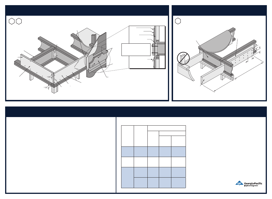
RIM CLOSURE AND DECK ATTACHMENT
Vertical load transfer of rim board = 4850 plf
Starter joist
Blocking where
required by local
codes for lateral
load transfer and/or
optional blocking for
diaphragm nailing
(3) 8d nails at corners
FiberStrong
rim board
One 2x4 min. with
1
⁄
8
9 gap
at top, fasten with 8d box
nails from each web
into 2x_.
Do not butt ends
at joist location.
FiberStrong rim board
Sheathing
Siding
Weather Barrier
CAUTION: The lag screw should be
inserted in a lead hole by turning with
a wrench, not by driving with hammer.
Over-torquing can significantly reduce
the lateral resistance of the screw
and therefore should be avoided.
8d nails
top and
bottom flange
FiberStrong rim board
1
⁄
2
9 sheathing with
weather barrier
Metal flashing–
under weather
barrier at top,
over weather
barrier at
bottom
Check local building code for appropriate detail in areas of high lateral load.
X-bridging or Wood I Beam
™
blocking panels
(see detail F2) required at cantilevers and
continuing for 48 on each side
of cantilevered area.
Load bearing wall
not allowed.
2x8 min. (designed by others)
nailed to backer block and web
with 2 rows of 10d nails at 69 o.c.
and clinched when possible.
Backer block depth (detail
F13) to match that of full-depth
filler blocking (detail F11).
Install backer tight to bottom
flange. Nail with 2 rows of 10d
nails at 69 o.c. and clinch.
CANTILEVER, DROPPED
29
69
48-0
9 min.
1 1/2 x L
48-0
9 max.
L
Uniform Loads Only
39
2x PT ledger attached with
1
⁄
2
9 diameter through-bolts with washers
and nuts or
1
⁄
2
9 lag screws with tip extending a minimum of
1
⁄
2
9 beyond
rim board. Capacity is 350 pounds per fastener. Bolt / lag screw
spacing to be determined by design vertical and lateral load. Lower
fastener may alternately be located in wall plate. Use high quality
caulk to fill holes and seal flashing.
Extend flashing below
2 x _ ledger and over siding.
Minimum 8d nails at 6” o.c.
toe-nail to plate, typical
Cantilevers for balconies
F5
F6
(no wall Load from above)
Installation Guide