Cantilevers for vertical building offsets, Concentrated wall load from above), Gp lam – Georgia-Pacific GP Lam LVL User Manual
Page 6: Lvl fastening requirements, Fastener clearances for multiple-ply members, Side loaded member
28-0
9
28-0
9 max.*
L
28-0
9
28-0
9 max.*
L
Cantilevers for vertical building offsets
(Concentrated wall Load from above)
GP Lam
®
LvL fastening requirements
3
1
⁄
2
9 Wide 5
1
⁄
4
9 Wide
79 Wide
Fastener Type
LVL Depth
2-Ply 1
3
⁄
4
9
3-Ply 1
3
⁄
4
9 1
3
⁄
4
9 + 3
1
⁄
2
9
4-Ply 1
3
⁄
4
9
2-Ply
2-Ply
1
3
⁄
4
9 + 3
1
⁄
2
9
3
1
⁄
2
9
10d (0.1289 x 39) 7
1
⁄
4
9≤d<149 3 rows @ 12” o.c. 3 rows @ 12” o.c. (ES)
3 rows @ 12” o.c.
-
3 rows @ 12” o.c. (ES) -
Nails d≥149
4 rows @ 12” o.c. 4 rows @ 12” o.c. (ES) 4 rows @ 12” o.c.
-
4 rows @ 12” o.c. (ES) -
16d (0.1629 x 3
1
⁄
2
9) 7
1
⁄
4
9≤d<149 2 rows @ 12” o.c. 2 rows @ 12” o.c. (ES)
2 rows @ 12” o.c.
-
2 rows @ 12” o.c. (ES) -
Nails
d≥149
3 rows @ 12” o.c. 3 rows @ 12” o.c. (ES) 3 rows @ 12” o.c.
-
3 rows @ 12” o.c. (ES) -
1
⁄
2
9 Through Bolts
2 rows @ 24” o.c. 2 rows @ 24” o.c.
2 rows @ 24” o.c.
SDS
1
⁄
4
9 x 3
1
⁄
2
9, WS35,
2 rows @ 24” o.c. 2 rows @ 24” o.c. (ES) 2 rows @ 24” o.c.
-
2 rows @ 24” o.c. (ES) -
3
3
⁄
8
9 TrussLok
SDS
1
⁄
4
9 x 69, WS6
d≥7
1
⁄
4
9
-
-
2 rows @ 24” o.c. (ES)
59 TrussLok
- 2 rows @ 24” o.c.
-
6
3
⁄
4
9 TrussLok
-
-
2 rows @ 24” o.c.
NOTES:
1. Minimum fastening requirements for depths less than 7
1
⁄
4
9 require special consideration. Please contact your technical representative.
2. Three general rules for staggering or offsetting for a certain fastener schedule: (1) if staggering or offsetting is not referenced, then none is required; (2) if staggering is referenced, then fasteners
installed in adjacent rows on the front side are to be staggered up to one-half the o.c. spacing, but maintaining the fastener clearances above; and (3) if “ES” is referenced, then the fastener
schedule must be repeated on each side, with the fasteners on the back side offset up to one-half the o.c. spacing of the front side (whether or not it is staggered).
GENERAL NOTES:
1. Confirm the adequacy of the beam (depth and width) for carrying the designated load.
2. Stress level for nail, bolt and screw values is 100%. Increases of 15% for snow loaded roof
conditions or 25% for non-snow roof conditions are permitted.
3. Top and bottom rows of fasteners should be as shown in the fastener clearances detail.
For staggered fastening patterns, the maximum end distance applies to all rows.
4. All fasteners must have the length fully embedded, but must not be over-driven, countersunk,
or over-tightened.
5. Bolt holes are to be
1
⁄
32
9 to
1
⁄
16
9 diameter larger than the bolts. Bolts must meet or exceed
ASTM A 307 or SAE J429 Grades 1 or 2. Every bolt must extend through the full width of the
member. Use washers not less than a standard cut washer under the head and nut meeting
ANSI B18.22.1.
6. 79 wide beams should only be side-loaded when loads are applied to both sides, when the
lesser side load plf is at least 25% of the opposite side, or when the beam is otherwise
restrained to minimize rotation.
7. For beam depths < 7
1
⁄
4
9, the maximum beam width must not exceed the beam depth and
all fasteners must be staggered up to one-half the required o.c. spacing. For depths ≥7
1
⁄
4
9,
the maximum beam thickness is 79.
8. Fastening recommendations are based on the 2005 National Design Specification for
Wood Construction (NDS) or fastener manufacturer’s design information.
9. SDS structural screws are produced by Simpson Strong-Tie Company, Inc., WS structural
screws are produced by United Steel Products Company, and TrussLok structural screws
are produced by FastenMaster-OMG, Inc. Structural screws must be installed per
manufacturer’s recommendations.
2 Rows “ES” (offset on back side)
3 Rows “ES” (offset on back side)
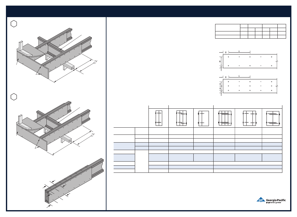
fastener Clearances for multiple-Ply members
Fastener
A B C D
Min. Min. Max. Min. Max. Min.
10d & 16d Nails
2( 2(
6( 4( 12( 3(
Bolts & Screws
2( 4( 12( 4( 24( 3(
minimum fastening
requirements for
top Loaded members
Spacings closer than those above may be acceptable, but require special
consideration. Contact your technical representative.
Side Loaded member
For side loaded members additional fasteners may be required. Please refer to the GP Engineered Lumber Product Guide.
59
69
69
69
29
69
69
DOUBLE REINFORCEMENT NAILING PATTERN
Note: FiberStrong rim board or 48/24 APA Rated sheathing (strength axis horizontal)
required both sides of joist. Depth must match full depth of joist.
Nail to joist flanges with 8d nails at 69 o.c.
Offset nailing on opposite side of flange to
avoid splitting.
23
⁄
32
9 APA
Rated sheathing
or FiberStrong
rim board
X-bridging or Wood I Beam
blocking
panels (see detail F2) required at
cantilevers and continuing for 48 on
each side of cantilevered area.
One 8d
nail at top and
bottom flange
* Cantilever length must not exceed
1/4 the adjacent span (L).
For allowable wall/roof loads on
cantilever, use cantilever table,
FASTBeam software or
contact Georgia-Pacific.
CANTILEVER, REINFORCED
Single Sheathing/Rim Board (Option I)
Note: FiberStrong rim board or 48/24 APA Rated sheathing (strength axis horizontal) required one
side of joist. Depth must match full depth of joist. Nail to joist flanges with 8d nails at 69 o.c.
23
⁄
32
9 APA
Rated sheathing
or FiberStrong
®
rim board
X-bridging or Wood I Beam
™
blocking panels (see detail F2)
required at cantilevers and
continuing for 48 on each
side of cantilevered area.
One 8d
nail at top and
bottom flange
* Cantilever length must
not exceed 1/4 the
adjacent span (L).
For allowable wall/roof loads on
cantilever, use cantilever table,
FASTBeam
®
software or
contact Georgia-Pacific.
C2
CANTILEVER, REINFORCED
Double Sheathing/Rim Board (Option II)
C3
Installation Guide