General Machine Products 89000 Cable Blowing Machine(Current) User Manual
Page 34
Page 34 of 64
General Machine Products Co., Inc.
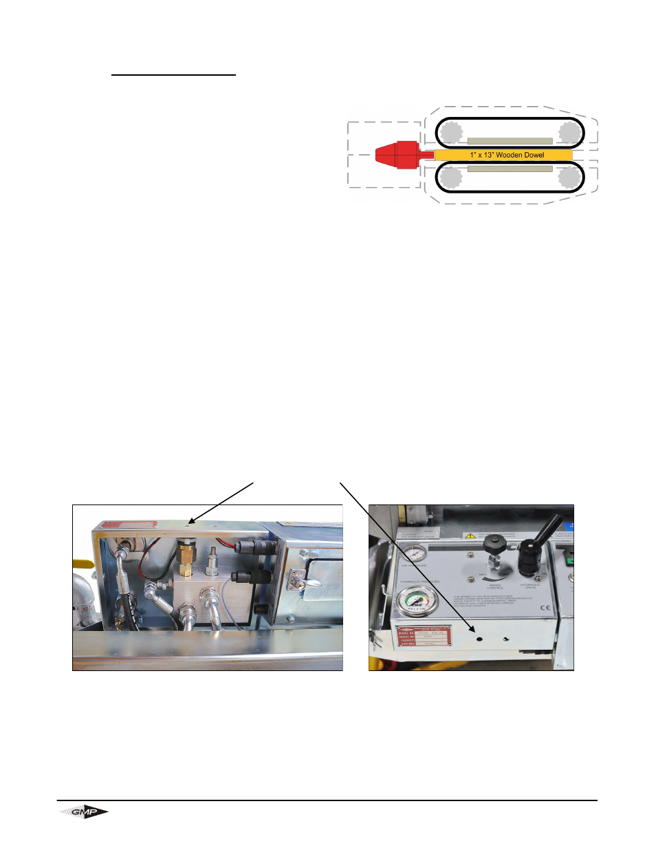
TO SET PRESSURE SWITCH FOR SMALL DIAMETER .47 INCH OD (12MM) OR UNDER
OR FLEXIBLE CABLE
Clamp a piece of 1” O.D. dowel/round bar x 13”
long between top and bottom housings so it butts
up to the air chamber mounted collets (in effect
placing the motors in stall mode). Note: The be-
low procedure will put the unit in a hydraulic by-
pass condition and will rapidly heat the oil. Try to
keep the time in bypass to a minimum as the
heated oil could change the readings
1. Connect the electric lead to the power pack and blowing machine.
2. Rotate the speed control knob fully counter-clockwise to “MIN”.
3. Press the on/off button (to turn the electric’s on).
4. Turn the pressure switch adjusting screw fully in (clockwise) using a 3/32 inch Allen key
through the hole in the front of the panel (see fig. 2).
5. Start the power pack.
6. Turn the hydraulic on/off valve to “on” position.
7. Turn the speed control knob towards “max” (clockwise) until the pressure gauge reads 870
psi (60 bar).
8. Turn the pressure switch adjusting screw slowly out (counter-clockwise) until the power
pack stops.
9. Turn the speed control knob to minimum (turned fully counter-clockwise).
10. After 5 seconds has elapsed restart the power pack and turn the speed control knob slow-
ly towards ”MAX” and note what pressure the power pack stops, repeat the procedure and
fine adjust the pressure switch adjusting screw until 870 psi (60 bar) is achieved.
When installation of cables of diameters .47inch (12mm) O.D. and above are re-
quired again, reset the pressure relief valve and pressure switch to:
Pressure relief valve 1600 psi (110 bar)
Pressure switch 1450 psi (100 bar)
Pressure Switch
Fig 2
Note: