General Machine Products 89000 Cable Blowing Machine(Current) User Manual
Page 33
Page 33 of 64
General Machine Products Co., Inc.
PROCEDURE FOR SETTING THE RELIEF VALVE AND PRESSURE SWITCH FOR
CABLE SIZES .24-.47 inch (6-12mm) OD
When installing small diameter cables with “soft/flexible” characteristics, it will be necessary to
reduce the pressure relief valve and pressure switch settings to help prevent the cable from
buckling or being jammed in the air chamber mounted collet. The pressure relief valve should
be set to 1015 psi (70 bar). The pressure switch should be set to 870 psi (60 bar). For
“softer/more flexible” cables the above values may have to be reduced proportionally to ena-
ble successful installation.
TO SET PRESSURE RELIEF VALVE FOR SMALL DIAMETER, .47 INCH OD (12MM) OR
UNDER OR FLEXIBLE CABLE
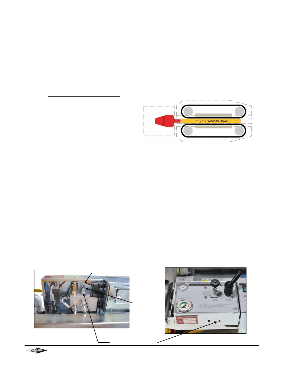
Clamp a piece of 1” O.D. dowel/round bar x
13” long in the drive belts so it butts up to the
air chamber mounted collets (in effect placing
the motors in stall mode). Note: The below
procedure will put the unit in a hydraulic by-
pass condition and will rapidly heat the oil. Try
to keep the time in bypass to a minimum as the heated oil could change your readings.
1. Connect the hydraulic hoses and start the power pack. With the electric control panel
switched “off”, turn hydraulic on/off valve to the “on” position.
2. Rotate the speed control knob fully clockwise to “MAX” and observe pressure gauge read-
ing of approximately 1600 psi (110 bar).
3. Loosen the 1/2” lock nut and adjust pressure relief valve (see fig. 1) using a 5/32” Allen
wrench until the pressure gauge pointer drops to 1015 psi (70 bar).
4. Rotate the speed control knob counter-clockwise (towards “MIN”) until the pressure gauge
reads 0 psi (0 bar).
5. Rotate the speed control knob again, fully clockwise to “MAX” and re-check pressure
gauge reading of approximately 1015 psi (70 bar).
6. Re-adjust the relief valve slightly if needed until 1015 psi (70 bar) is indicated on the
gauge. Finally tighten the lock nut while preventing the relief valve adjustment from turn-
ing.
7. Rotate the speed control knob again, fully clockwise to “MAX” and re-check the pressure
reading of approximately 1015 psi (70 bar) after lock nut is tightened. If different, readjust.
Lock Nut
Adjusting Screw
Fig1
Pressure Relief Valve