Warning – Gast R7P User Manual
Page 3
Select fuses, motor protective switches or thermal
protective switches to provide protection. Fuses act as
short circuit protection for the motor, not as protection
against overload. Incoming line fuses must be able to
withstand the motorʼs starting current. Motor starters
with thermal magnetic overload or circuit breakers
protect motor from overload or reduced voltage
conditions. Motors without automatic restart require
thermal protection or magnetic over-current cutout to
prevent motor overloading from one phase in a 3-phase
circuit, high starting frequency or jammed blower.
The power required will rise as differential pressure
increases. The wiring diagram attached to the product
or on page 6 of this manual provides required electrical
information. Large motors have two diagrams, one for
50Hz wiring specifications and the other for 60Hz wiring
specifications. Check that the power source is correct
to properly operate the dual-voltage motor. If additional
information is required, please consult your Gast
Distributor/Representative.
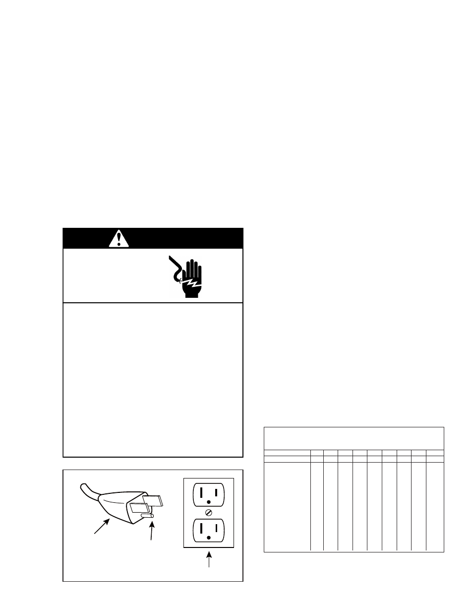
Model with a power supply cord:
This product must be grounded. For either 120-volt or
220/240-volt circuits connect power supply cord
grounding plug to a matching grounded outlet. Do not
use an adapter. (See DIAGRAM A)
Model that is permanently wired:
This product must be connected to a grounded,
metallic, permanent wiring system, or an equipment
grounding terminal or lead on the product.
Power supply wiring must conform to all required safety
codes and be installed by a qualified person. Check
that supply voltage agrees with that listed on product
nameplate.
Extension cords:
Use only a 3-wire extension cord that has a 3-blade
grounding plug. Connect extension cord plug to a
matching 3-slot receptacle. Do not use an adapter.
Make sure your extension cord is in good condition.
Check that the gage wire of the extension cord is the
correct size wire to carry the current this product will
draw.
An undersized cord is a potential fire hazard, and will
cause a drop in line voltage resulting in loss of power
causing the product to overheat. The following table
indicates the correct size cord for length required and
the ampere rating listed on the product nameplate. If in
doubt, use the next heavier gage cord. The smaller the
gage number, the heavier the wire gage.
Check with a qualified electrician or serviceman if the
grounding instructions are not completely understood,
or if you are not sure whether the product is properly
grounded. Do not modify the plug provided. If it will not
fit the outlet, have the proper outlet installed by a
qualified electrician.
In the event of an electrical short circuit, grounding
reduces the risk of electric shock by providing an
escape wire for the electric current. This product may
be equipped with a power supply cord having a
grounding wire with an appropriate grounding plug.
The plug must be plugged into an outlet that is properly
installed and grounded in accordance with all local
codes and ordinances.
Electrical Connection
Ꮨ
This product must be properly grounded.
Do not modify the plug provided. If it will not
fit the outlet, have the proper outlet installed
by a qualified electrician.
If repair or replacement of the cord or plug is
necessary, do not connect the grounding wire
to either flat blade terminal. The wire with
insulation that is green or green with yellow
stripes is the grounding wire.
Check the condition of the power supply wiring.
Do not permanently connect this product to
wiring that is not in good condition or is
inadequate for the requirements of this product.
Failure to follow these instructions can result in
death, fire or electrical shock.
WARNING
Electrical Shock Hazard
Grounded Plug
Grounding Pin
Grounded Outlet
120-volt grounded connectors
shown. 220/240-volt grounded
connectors will differ in shape.
DIAGRAM A
Minimum gage for extension cords
Amps
Volts
Length of cord in feet
120v
25 50
100 150 200 250 300 400 500
240v
50 100 200 300 400 500 600 800 1000
0-2
18 18
18
16
16
14
14
12
12
2-3
18 18
16
14
14
12
12
10
10
3-4
18 18
16
14
12
12
10
10
8
4-5
18 18
14
12
12
10
10
8
8
5-6
18 16
14
12
10
10
8
8
8
6-8
18 16
12
10
10
8
6
6
6
8-10
18 14
12
10
8
8
6
6
4
10-12
16 14
10
8
8
6
6
4
4
12-14
16 12
10
8
6
6
6
4
2
14-16
16 12
10
8
6
6
4
4
2
16-18
14 12
8
8
6
4
4
2
2
18-20
14 12
8
6
6
4
4
2
2
3