Correct use, Incorrect use, Function – EUCHNER SN 8 mm User Manual
Page 3: Switching elements / pin assignment, Installation, Protection against environmental effects, Electrical connection, Function test, Service and inspection, Technical data
Operating Instructions Precision Multiple Limit Switches GL, GS, SB, SN 8 mm
Correct use
Precision multiple limit switches are used for posi-
tioning and controlling machines and in industrial
installations.
Correct use includes compliance with the relevant
requirements for installation and operation, in
particular
EN 60204-1, Electrical equipment of machines
EN 1050, Safety of machinery. Principles for risk
assessment.
Incorrect use
Precision multiple limit switches with switching ele-
ment ES 552 und ES 614 (snap-action switching
elements not positively driven) must not be used
in safety circuits.
Function
Precision multiple limit switches possess several
switching elements arranged in a row.
The switching elements are actuated by means of
plungers. Different plunger types and trip dogs are
used depending on the application (operating point
accuracy and approach speed).
The plunger is actuated by trip dogs which are
mounted with an interference fit in trip rails.
The year of manufacture of the switch is indicated
in the production code.
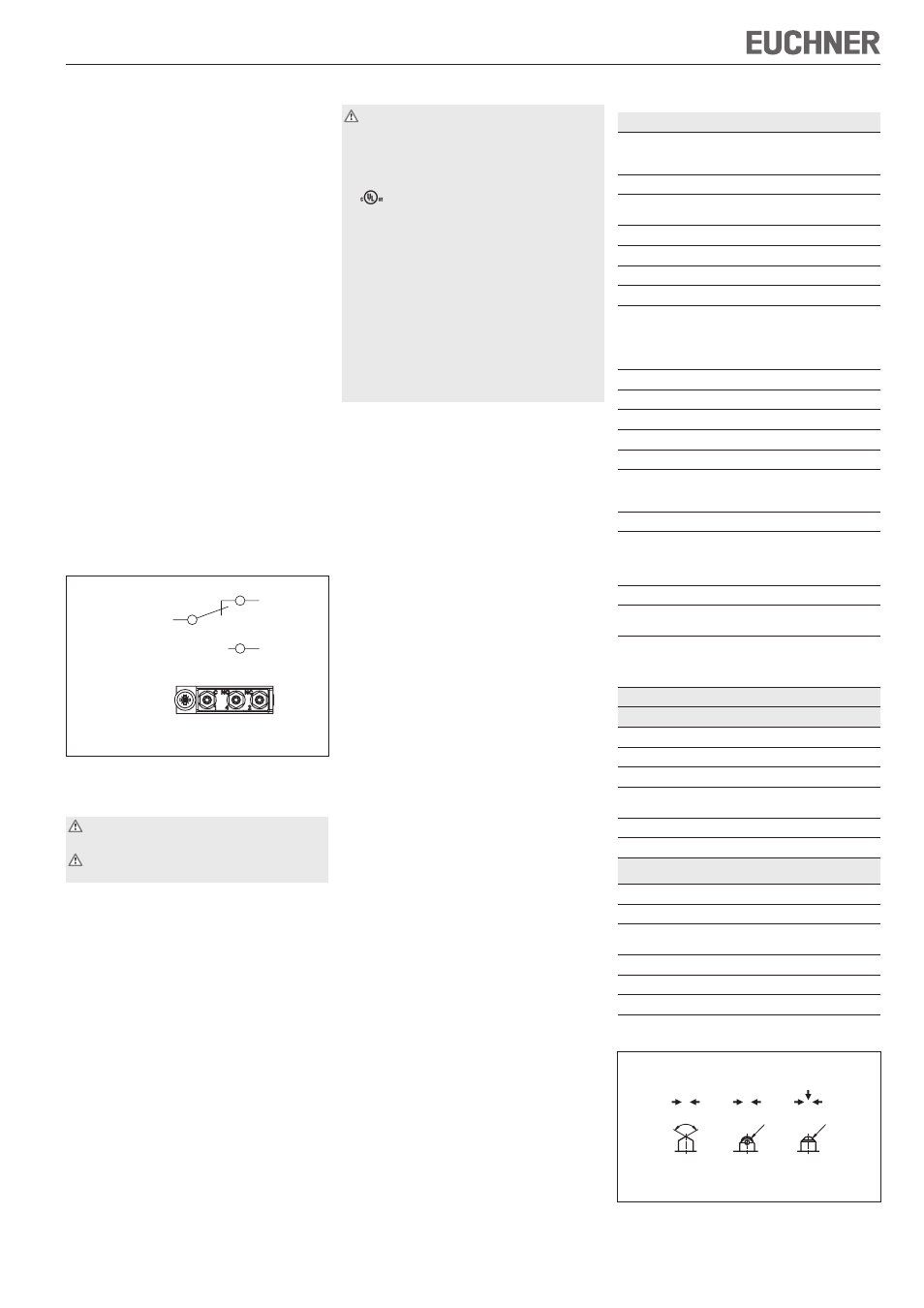
Switching elements / pin assignment
Fig. 1: Switching elements and pin assignment
Installation
This unit is to be assembled by authorized
personnel only.
Precision multiple limit switches must not be
used as an end stop.
Fit precision multiple limit switches so that
connection cables and plug connectors are not
damaged by moving parts of the machine
sealing is ensured on cable entry through the
base.
Protection against environmental effects
Safety venting valves are used to equalize the pres-
sure to protect against the pumping action of the
plunger. They must not be sealed with paint.
Mask plunger, plunger guide, safety venting valves
and rating plate during painting work!
Electrical connection
Electrical connection must be performed by
authorized personnel only.
The following applies for switches with UL ap-
proval:
For use and applications as per the requirements
of
, a class 2 power supply or a class 2
transformer according to UL1310 or UL1585
must be used.
Connection cables for precision multiple limit
switches installed at the place of use must be sepa-
rated from all moving and permanently installed
cables and un-insulated active elements of other
parts of the system which operate at a voltage of
over 150 V. A constant clearance of 50.8 mm must
be maintained. This does not apply if the moving
cables are equipped with suitable insulation materi-
als which possess an identical or higher dielectric
strength compared to the other relevant parts of
the system.
Open switch cover
Conductor cross-section 0.14 ... 1.0 mm²
For pin assignment see Figure 1
Fit suitable cable gland with captive O-ring
Seal cable carefully. Sealing ring must be matched
to the diameter of the cable
Tighten screws for connections to the switching
element to 0.2 Nm
Close switch cover and tighten cover screws to
0.5 Nm.
Function test
Mechanical function test
Actuate plunger and check the switching func-
tion.
Electrical function test
Check correct function.
Service and inspection
No servicing is required, but regular inspection
of the following is necessary to ensure trouble-free
long-term operation:
correct switching function
secure mounting of components
precise adjustment of trip dog in relation to multiple
limit switch
dirt and wear
sealing of cable entry
loose cable connections.
Exclusion of liability under the following
conditions:
if the unit is not used for its intended purpose
non-compliance with safety regulations
installation and electrical connection not per-
formed by authorized personnel
failure to perform functional checks.
Technical data
Parameter
Value
Housing material
Series
GL, GS
SB, SN
Sand-cast aluminum, anodized
Die-cast aluminum, anodized
Plunger material
Stainless steel
Degree of protection accord-
ing to IEC 60529
IP 67
Mech. operating cycles
30 x 10
6
Actuation frequency
≤ 200 min
-1
Ambient temperature
-5 ... +80 °C
Installation position
Any
Approach speed, max.
Plunger Chisel D
Roller R
(slide bearing)
Ball K
20 m/min
50 m/min
8 m/min
Approach speed, min.
0.01 m/min
Actuating force
≥ 15 N
Switching element
1 changeover contact
Switching principle
Snap-action switching element
Switching hysteresis max.
0.1 mm
Contact material
ES 552
ES 614
Silver
Gold cross cut contacts
Connection type
Screw terminal
Tightening torque
Screw terminal
(Hexagon socket head screw
AF 1.27 mm)
0.2 Nm
Conductor cross-section
0.14 ... 1.0 mm
2
Rated impulse
withstand voltage
U
imp
= 2.5 kV
Rated insulation voltage
with cable entry
with plug connector
U
i
= 250 V
U
i
= 50 V
Rated data for the switching elements
ES 552
Conv. thermal current I
th
6 A
Utilization category AC-15
230 V / 2 A
Utilization category DC-13
24 V / 2 A
Switching current, min. at
Switching current
10 mA
DC 24 V
Short circuit protection
6 A gG
Mechanical life
up to 10 x 10
6
operating cycles
ES 614
Conv. thermal current I
th
2 A
Utilization category DC-13
30 V / 1 A
Switching current, min. at
Switching current
1 mA
DC 5 V
Short circuit protection
2 A gG
Mechanical life
up to 10 x 10
6
operating cycles
Ideal application
1 mA; 5 V ... 0.3 A; 30 V
Figure 2: Plungers and approach directions
D
R
K
R4
R4
120
-5°
Preferred approach directions
ES 552
ES 614
1
2
4
1
4 (NO)
2 (NC)
(C)
Top view
on the switching element