X1 x2 – EUCHNER GL 12/16 mm User Manual
Page 6
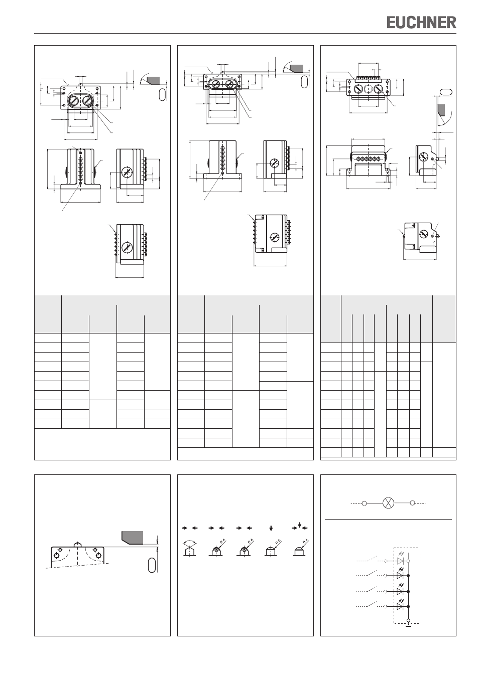
Operating Instructions Precision Multiple Limit Switches RG, GS, GL12/16 mm
n
Plunger spacing
Number
l
1
= 12
l
1
= 16
of
Housing
Housing
plungers
l
2
material
l
2
material
2
70
70
3
70
82
Die-cast
4
82
Die-cast
96
aluminum,
5
96
aluminum,
112
anodized
6
112
anodized
130
8
130
160
10
160
192
Sand-cast
12
179
aluminum,
14
208
Sand-cast
256
anodized
16
226
aluminum,
288
18
256
anodized
–
–
20
288
–
–
n
Plunger spacing
Number
l
1
= 12
l
1
= 16
of
Housing
Housing
plungers
l
2
material
l
2
material
2
70
70
3
80
90
Die-cast
4
90
Die-cast
105
aluminum,
5
105
aluminum,
120
anodized
6
120
anodized
140
8
140
170
10
170
200
Sand-cast
12
200
Sand-cast
240
aluminum
14
240
aluminum,
–
–
16
240
anodized
–
–
Plunger spacing
n
l
1
= 12
l
1
= 16
Housing
Number
material
of
l
2
l
3
l
4
l
2
l
3
l
4
plungers
2
84
66
52
84
66
52
A
3
84
66
52
A
100 82
68
4
100 82
68
114 98
84
5
114 98
84
132 114 100
6
132 114 100
148 130 116
Sand-cast
8
148 130 116
180 162 148
aluminum,
10
180 162 148
B
212 194 180
B
anodized
12
199 178 167
+
244 226 212
+
14
228 210 196
C
276 258 244
C
16
244 226 212
308 290 276
18
276 258 244
340 322 308
20
308 290 276
–
–
–
–
–
Cable entry
Cable entry
Illustration with chisel plunger, plunger type dependent on version
Illustration with chisel plunger, plunger type dependent on version
Illustration with chisel plunger, plunger type dependent on version
Figure 5: Mounting RG/GS/GL...-508 and RG/GS/
GL...-514 for safety circuits
4
-0
.5
Figure 6: Plungers and approach directions
Figure 2: Dimension drawing RG...
Figure 3: Dimension drawing GS...
Figure 4: Dimension drawing GL...
Figure 7: Connection LED indicators
Preferred approach directions
(* only with switching element ES 502E)
120°
-5°
D
R
B
W
K*
Chisel
Roller
Roller
Dome
Ball
Slide
Ball
bearing
bearing
LE024GE in design RG with switching element ES514 and
plunger spacing 12 mm
RD
RD
RD
Switching elements
LED printed cir
cuit boar
d
LE060, LE110 and LE220
X1
X2
40
72
80
6,6
6
22
8
50
37
45
6
±0,
1
8
m
ax.
70
3
0
° max
.
100
14
l
2
120
85
50
80
50
l
1
30
n
ø10
LED
5
-1,5
Operating point
Groove with sealing ring
Dog
F
ree position
Reference surface
Cable entry
M25x1.5
Cable
entry
M25x1.5
Version with LED function
display
Safety venting valve
Safety venting valve
6
8
max.
30
°
max
.
l
1
30
n
30
45
26
40
80
82
98
6,6
4
22
8
28
14
l
2
115
45
36
68 (95*)
100
ø10
LED
5
-1,5
* Only with switching element
ES 514
Operating point
Groove with sealing ring
Dog
F
ree position
Reference surface
Cable
entry
M25x1.5
Version with LED function
display
Cable entry
M25x1.5
Safety venting valve
l
1
n
40
l
3
4
23
8
30
B
A C
30
50
20
50
90
l
4
ø6,6
l
2
14
ø11
100
38
56
6
8 max.
30
°
ma
x.
ø
10
LED
62 (95*)
5
-1,5
Reference surface
Dog
Cable entry
M25x1.5
Cable entry
M25x1.5
Free position
* Only with switching element
ES 514
Version with LED function
display
Safety
venting
valve
Safety
venting
valve
Operating point