Bryant 559F User Manual
Page 2
—
2
—
LEGEND
MM — Motormaster® Head Pressure Control Device
*Use the 32LT900301 for 208/230 units. Use the 32LT900611 for 460-v
units.
†Not required on models with the loss-of-charge switch on the liquid
line.
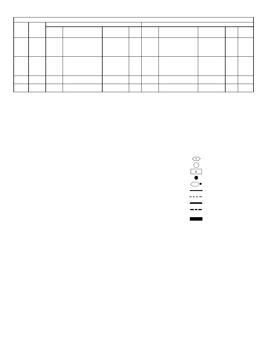
LEGEND (FIG. 1-16, 20 AND 21)
LOWER OUTDOOR AMBIENT OPERATION ACCESSORIES
Unit
559F/
579F
Std Min.
Operating
Temp
Mild Ambient Control
Low Ambient Control
Min.
Operating
Temp (F)
Acy Kit Part No.
Required (Quantity)
Accessory
Name
Wiring
Fig.
No.
Min.
Operating
Temp (F)
Acy Kit Part No.
Required (Quantity)
Accessory
Name
Wiring
Fig.
No.
Sensor
Location
Fig. No.
180
40
10
CRWINSTR001A00,
CRLOWAMB001A00
Winter Start Kit
10 F Ambient Kit
22,23
–20
CRWINSTR001A00,
CRLOWAMB001A00,
32LT900301
OR
32LT900611*†
Winter Start Kit,
10 F Ambient Kit,
–20 F MM I
22,23,
24
25
216
40
10
CRWINSTR001A00† (2),
CRLOWAMB001A00
Winter Start Kit
10 F Ambient Kit
22,23
–20
CRWINSTR001A00 (2),
CRLOWAMB001A00,
32LT900301
OR
32LT900611*†
Winter Start Kit,
10 F Ambient Kit,
–20 F MM I
22,23,
24
25
240
40
25
CRWINSTR001A00,
CRLOWAMB002A00
Winter Start Kit
25 F Ambient Kit
22,26
–20
CRWINSTR001A00 (2),
30GT910079††
Winter Start Kit,
–20 F MM III
22,27
28
300
40
25
CRWINSTR001A00,
CRLOWAMB002A00
Winter Start Kit
25 F Ambient Kit
22,26
–20
CRWINSTR001A00 (2),
30GT910079††
Winter Start Kit,
–20 F MM III
22,27
28
AHA
— Adjustable Heat Anticipator
BR
— Burner Relay
BRK W/AT
— Breaks With Amp Turns
C
— Contactor, Compressor
CAP
— Capacitor
CB
— Circuit Breaker
CC
— Cooling Compensator
CH
— Crankcase Heater
CLO
— Compressor Lockout
CLS
— Compressor Lockout Switch
COMP
— Compressor Motor
CPM
— Compressor Protection Module
CR
— Control Relay
CT
— Current Transformer
DM
— Damper Motor
DU
— Dummy Terminal
EAS
— Economizer Actuator
Auxiliary Switch
EMC
— Economizer Motor Contactor
EQUIP
— Equipment
FL
— Fuse Link
FLA
— Full Load Amps
FPT
— Freeze-Protection Thermostat
FS
— Flame Sensor
FU
— Fuse
GND
— Ground
GVR
— Gas Valve Relay
HC
— Heater Contactor
HPS
— High-Pressure Switch
HS
— Hall Switch
HTR
— Heater
HV
— High-Voltage
I
— Ignitor
IDM
— Induced-Draft Motor
IFC
— Indoor (Evaporator) Fan Contactor
IFCB
— Indoor (Evaporator) Fan
Circuit Breaker
IFM
— Indoor (Evaporator) Fan Motor
IFR
— Indoor (Evaporator) Fan Relay
IGC
— Integrated Gas Controller
L
— Light
LED
— Light-Emitting Diode
LLS
— Liquid Line Solenoid
LOR
— Lockout Relay
LPS
— Low-Pressure Switch
LS
— Limit Switch
MAT
— Mixed-Air Thermostat
MGV
— Main Gas Valve
NEC
— National Electrical Code
NEUT
— Neutral
OAT
— Outdoor-Air Thermostat
OFC
— Outdoor (Condenser) Fan Contactor
OFM
— Outdoor (Condenser) Fan Motor
OP
— Overcurrent Protection
PL
— Plug Assembly
PRI
— Primary
QT
— Quadruple Terminal
RS
— Rollout Switch
SEN, SN — Sensor
SR
— Solenoid Relay
SW
— Switch
TB
— Terminal Block
TC
— Thermostat Cooling
TH
— Thermostat Heating
TRAN
— Transformer
U
— Unloader
UR
— Unloader Relay
Terminal (Marked)
Terminal (Unmarked)
Terminal Block
Splice
Splice (Marked)
Factory Wiring
Field Control Wiring
Field Power Wiring
Accessory or Optional Wiring
To indicate common poten-
tial only, not to represent
wiring.