Operating instructions safety switch nq..vz – EUCHNER NQxxVZ User Manual
Page 3
Operating Instructions Safety Switch NQ..VZ
Correct use
Safety switches series NQ are interlocking devices
without guard locking.
In combination with a separating safety guard, this
safety component prevents the safety guard from
being opened while a dangerous machine movement
is being performed. A stop command is triggered if
the safety guard is opened during the dangerous
machine function.
The safety switches series NQ comply with the
regulations of EN 60947-5-1, Annex K and comply
with the requirements of the employers’ liability
insurance associations for machines, installations and
personnel protection.
Before safety switches are used, a risk assessment
must be performed on the machine in accordance
with
EN ISO 13849-1, Safety of machinery. Safety related
parts of control systems. General principles for
design
EN ISO 14121, Safety of machinery. Risk
assessment. Principles
IEC 62061, Safety of machinery. Functional safety
of safety-related electrical, electronic and
programmable electronic control systems.
Correct use includes compliance with the relevant
requirements for installation and operation,
particularly
EN ISO 13849-1, Safety of machinery. Safety related
parts of control systems. General principles for
design
EN 1088, Safety of machinery. Interlocking devices
associated with guards. Principles for design and
selection
EN 60 204-1, Electrical equipment of machines
Important:
The user is responsible for the integration of the
device in a safe overall system. For this purpose
the overall system must be validated, e.g. in
accordance with EN ISO 13849-2.
If the simplified method according to section 6.3
EN ISO 13849-1:2008 is used for validation, the
Performance Level (PL) may be reduced if several
devices are connected one after the other.
If a product data sheet is included with the product,
the information on the data sheet applies in case of
discrepancies with the operating instructions.
Safety precautions
Safety switches fulfill a personal protection function.
Incorrect installation or tampering can lead to severe
injuries to personnel.
Safety components must not be bypassed
(bridging of contacts), turned away, removed or
otherwise rendered ineffective.
On this topic pay attention in particular to the
measures for reducing the possibility of bypassing
from EN 1088:1995+A2:2008, section 5.7.
The switching operation may only be triggered
by actuators specially provided for this purpose
which are permanently connected to the
protective guard.
Mounting, electrical connection and setup only
by authorized personnel.
Function
The safety switch signals that the safety guard is
closed.
The switch does not perform guard locking!
Closing
The safety contacts are closed by inserting the
actuator.
Opening
The safety contacts are positively opened by
withdrawing the actuator.
Mounting
Safety switches and actuators must not be used
as an end stop.
Mount the safety switch only in assembled
condition!
Assemble the safety switch so that
access to the switch is difficult for operating
personnel when the safety guard is open.
maintenance and replacement are possible.
Insert the actuator in the actuating head.
Mount the safety switch positively.
Permanently connect the actuator to the safety
guard using rivets or by welding.
Fit an additional stop for the movable part of the
safety guard.
Protection against environmental influences
A lasting and correct safety function requires that the
actuating head must be protected against the
penetration of foreign bodies such as swarf, sand,
blasting shot, etc.
Cover the unused actuating slot with the slot cover.
Cover the actuating slot, the actuator and the rating
plate during painting work!
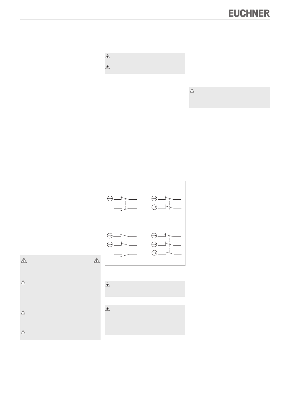
Switching elements and switching functions
Fig. 1: Switching elements and switching functions
Electrical connection
When choosing the insulation material, pay
attention to the over-temperature in the housing
(depending on the operating conditions)!
Functional check
Warning! Danger of fatal injury as a result of faults
in installation and functional check.
Before carrying out the functional check, make
sure that there are no persons in the danger
area. Observe the valid accident prevention
regulations.
After installation and any fault, the safety function
must be fully checked. Proceed as follows:
Mechanical function test
The actuator must slide easily into the actuating
head. Close the safety guard several times to check
the function.
Electrical function test
1. Switch on operating voltage.
2. Close all safety guards.
The machine must not start automatically.
3. Enable operation in the control system.
4. Open the safety guard.
The machine must switch off and it must not be
possible to start it as long as the safety guard is
open.
Repeat steps 2 - 4 for each safety guard.
Inspection and service
If damage or wear is found, the complete switch
and actuator assembly must be replaced.
Replacement of individual parts or assemblies
is not permitted!
No servicing is required, but regular inspection
of the following is necessary to ensure trouble-free
long-term operation:
correct switching function
secure mounting of components
dirt and wear
sealing of cable entry
loose cable connections or plug connectors.
Note: The year of manufacture can be seen in the
bottom, right corner of the rating plate.
Exclusion of liability under the following
circumstances
incorrect use
non-compliance with safety regulations
installation and electrical connection not performed
by authorized personnel.
failure to perform functional checks.
EC declaration of conformity
The manufacturer named below herewith declares that
the product fulfills the provisions of the directive(s)
listed below and that the related standards have been
applied.
EUCHNER GmbH + Co. KG
Kohlhammerstraße 16
70771 Leinfelden-Echterdingen, Germany
Directives applied:
Machinery directive 2006/42/EC
Standards applied:
EN 60947-5-1:2004 + Cor.:2005 + A1:2009
EN 1088:1995+A2:2008
Leinfelden, July 2010
Dipl.-Ing. Michael Euchner
Director
Duc Binh Nguyen
Authorized representative empowered to draw up
documentation
The signed EC declaration of conformity is included
with the product.
33
12
OG/WH
OG
11
BU
34
BU/WH
OG/WH
12
31
BU/WH
BU
11
OG
32
21
12
BN/WH
BN
11
BU
OG
OG/WH
33
34
22
BU/WH
12
21
22
32
31
OG/WH
BU/WH
BU
11
BN
BN/WH
OG
11
02
12
03
Illustration: Door closed