Operating instructions safety switches sgp, Inspection and service, Declaration of conformity – EUCHNER SGPxxx User Manual
Page 5: Technical data
Operating Instructions Safety Switches SGP...
EUCHNER GmbH + Co. KG Kohlhammerstraße 16 D-70771 Leinfelden-Echterdingen Tel. +49/711/75 97-0 Fax +49/711/75 33 16 www.euchner.de [email protected]
Inspection and Service
If damage or wear is found, the complete switch
and actuator assembly must be replaced.
Replacement of individual parts or assemblies
is not permitted!
No servicing is required, but regular inspection of
the following is necessary to ensure trouble-free long-
term operation:
correct switching function
secure mounting of components
dirt and wear
sealing of cable entry
loose cable connections or plug connectors.
Safety switches must be exchanged completely after
2 million switching operations.
Note:The year of manufacture can be seen in the
bottom, right corner of the rating plate.
Exclusion of Liability under the Following
Conditions:
if the unit is not used for its intended purpose
non-compliance with safety regulations
installation and electrical connection not performed
by authorized personnel.
failure to perform functional checks.
Declaration of Conformity
See Annex 1 of the operating instructions.
Subject to technical modifications; no r
esponsibility is accepted for the accuracy of this information. © EUCHNER GmbH + Co. KG
097700-06-05/10 (translation of the original operating instructions)
34
34
42
42
22
22
12
12
12
12
22
22
42
42
34
34
14
22
22
42
42
34
34
21
22
14
13
11
12
22
21
22
12
14
22
21
11
13
21
41
42
34
33
33
41
21
11
22
21
11
12
12
11
21
22
11
21
41
33
33
34
42
41
14
13
21
22
13
21
41
33
33
34
42
41
1
2
3
4
5
6
4
5
6
7
8
11
9
3
2
1
10
PE
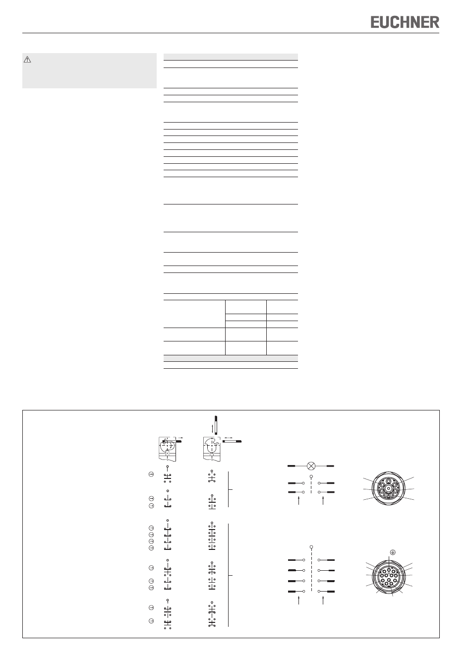
Version
Switching contacts
SGP.-528H...
1 NC contact +
1 NO contact
SGP.-538H...
2 NC contacts
SGP.-2121H...
4 NC contacts
SGP.-2131H...
3 NC contact +
1 NO contact
SGP.-3131H...
2 NC contact +
}2 NO contact
Door closed
Door open
Plug connector
SR6
Plug connector
SR11
2.
1
2.
2
3
4
1.
1.
6
5
Ordinal numbers of
switching elements
2.
1.
1.
2.
3.
3.
4.
4.
6
8
5
7
4
3
2
1
Ordinal numbers of
switching elements
Contact assignment with
plug connector
Connector
illustration
(view of safety switch
connection side)
(LED indicator with full wiring options, optional)
Figure 3: Switching elements and switching functions
Technical Data
Parameters
Value
Housing material
Reinforced thermoplastic
Degree of protection according to IEC 60529
SGP1...
IP67
SGP2...
IP65
Mech. Mechanical life
2x10
6
operations
Ambient temperature
-20 ... +80°C
Degree of contamination
(external, according ?to
3 (industrial)
EN 60947-1)
Installation position
Any
Approach speed, max.
20 m/min
Actuating force
25 N
Actuation frequency, max.
6700 / h
Extraction force
25 N
Retention force
10 N
Switching principle
Slow-action switching contact
Contact material
Silver alloy, gold flashed
Connection type
SGP1...
Screw terminal
SGP2...SR6
Plug connector SR6, 6-pin+PE
SGP2...SR11
Plug connector SR11, 11-pin+PE
Conductor cross-section (rigid/flexible)
SGP1...
0.34 ... 1.5 mm²
SGP2...SR6
0,5 ... 1.5 mm²
SGP2...SR11
0.5 mm²
Operating voltage for
L060
12 - 60 V
optional LED indicator
L110
110 V
(only SGP...528H/SGP...538H) L220
230 V
Switching voltage min.
12 V
at 10 mA
Switching current, min., at 24 V
1 mA
Short circuit protection
(control circuit fuse)
4 A gG
according to IEC 60269-1
Conv. thermal current I
th
4 A
Utilization category
SGP1.../SGP2...SR6
SGP2...SR11
according to EN 60947-5-1
AC-15
4 A 230 V
4 A 50 V
DC-13
4 A 24 V
4 A 24 V
Rated impulse
withstand voltage
U
imp
= 2.5 kV
U
imp
= 1.5 kV
Rated insulation
voltage
U
i
= 250 V
U
i
= 50 V
Reliability figures according to EN ISO 13849-1
B
10d
3 x 10
6