Installing or replacing the hid lamp, Ballast information, N o t e – ETC Source Four HID User Manual Supplement User Manual
Page 2
E T C U s e r M a n u a l S u p p l e m e n t
Source Four 70 and 150 Watt HID Fixtures
Source Four® User Manual Supplement for HID Fixtures
Page 2 of 3
Electronic Theatre Controls, Inc.
Installing or replacing the HID Lamp
Source Four HID fixtures ship with a lamp, which must be installed before you use the fixture.
Step 1:
Disconnect the power before installing the lamp.
Step 2:
Loosen the brass knurled bolt on the back of the lamp housing and pull out the lamp
burner assembly.
Step 3:
Remove the HID lamp from its box. Handle the lamp only by the base. Do not touch
the glass envelope.
Step 4:
Align the flat sides of the lamp base with the retention clips on either side of the
socket. The lamp is not polarized. It can be inserted either way in the socket.
Step 5:
Push down on the lamp base until the lamp seats firmly.
Step 6:
Reinstall the lamp burner assembly by aligning the lamp into the reflector and the
brass knurled bolt with the bolt hole and tightening the brass knurled bolt.
Ballast Information
• Acceptable voltage is 120V, 230V, or 277V (± 10%) 50/60 Hz only. Ensure that you have the
proper ballast for the input voltage at the installation.
• Room ambient temperature should not exceed 104°F (40°C).
• Lamp ignition voltage is 4.5kV, non-hot restrike.
• Ballast case temperature should not exceed 167°F (75°C).
• The ballast is attached to the Source Four fixture yoke by two screws and is non-remotable.
• The ballast appearance may vary slightly from the illustration.
• Some fixtures may require an additional mounting bracket to attach the ballast to the yoke.
Please contact ETC Customer Service for additional information regarding specific ballasts
and brackets.
N o t e :
To avoid premature lamp failure, do not touch the lamp glass. If you do, clean it
with isopropyl alcohol and a clean, lint-free cloth. Allow to dry before operation.
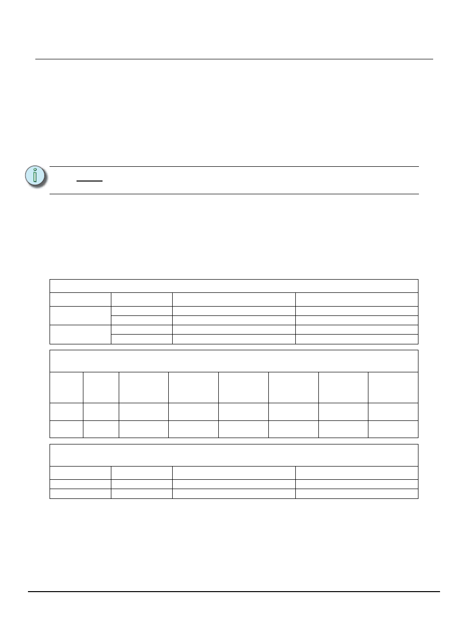
Operating Current and Breaker Loading Guidelines for UL Fixtures
Ballast Wattage
Run Current
Recommended 20A Breaker Load
Recommended 15A Breaker Load
150W
1.4A at 120V
Up to 10 units
Up to 7 units
0.65A at 277V
Up to 15 units
Up to 10 units
70W
0.7A at 120V
Up to 15 units
Up to 10 units
0.3A at 277V
Up to 20 units
Up to 15 units
Operating Current and Breaker Loading Guidelines for CE Fixtures
C-Curve Breakers
Ballast
Wattage
Run
Current
Recommended
30A Breaker
Load
Recommended
25A Breaker
Load
Recommended
20A Breaker
Load
Recommended
16A Breaker
Load
Recommended
13A Breaker
Load
Recommended
10A Breaker
Load
150W
0.7A
at 230V
Up to 25 units
Up to 20 units
Up to 15 units
Up to 12 units
Up to 10 units
Up to 8 units
70W
0.4A
at 230V
Up to 30 units
Up to 25 units
Up to 20 units
Up to 15 units
Up to 15 units
Up to 15 units
Operating Current and Breaker Loading Guidelines for CE Fixtures
B-Curve Breakers
Ballast Wattage
Run Current
Recommended 10A Breaker Load
Recommended 6A Breaker Load
150W
0.7A at 230V
Up to 5 units
Up to 3 units
70W
0.4A at 230V
Up to 8 units
Up to 5 units