Enerpac CT-604 User Manual
Page 2
2
4.0 INSTRUCTIONS
DANGER: Never attempt to relieve hydraulic
pressure by loosening a coupler. Trapped
hydraulic pressure can cause a loosened
coupler to dislodge unexpectedly with great force.
Serious personal injury or death will result if the
coupler becomes a projectile and strikes persons
working in the area.
WARNING!
Loosening a coupler may result
in an escape of high pressure oil that can
penetrate the skin. Serious personal injury or
death can result. Always use coupler bleed tool to
safely depressurize and remove couplers.
WARNING! Be sure that loads are supported
with blocking and cribbing before using bleed
tool. Actuator movement may occur when
hydraulic pressure is relieved. Serious personal injury
or death could occur if load shifts or drops.
WARNING! The CT-604 coupler bleed tool is
designed for a maximum hydraulic pressure
of 10,000 psi [700 bar]. Do not use the tool on
systems and components operating at higher
pressures.
Depressurize a hydraulically-locked coupler as
described in the following steps:
1. I f the hydraulic device is supporting a load, block
and crib the load as required, so that the load
will not shift or drop when hydraulic pressure is
relieved.
2. Check that the threads on the coupler half to be
depressurized are clean and in good condition.
Do not attempt to bleed a coupler if threads are
damaged.
3. Check that all threads on the bleed tool main body
and cap/bolt assemblies are clean and in good
condition. Do not use bleed tool if threads are
damaged.
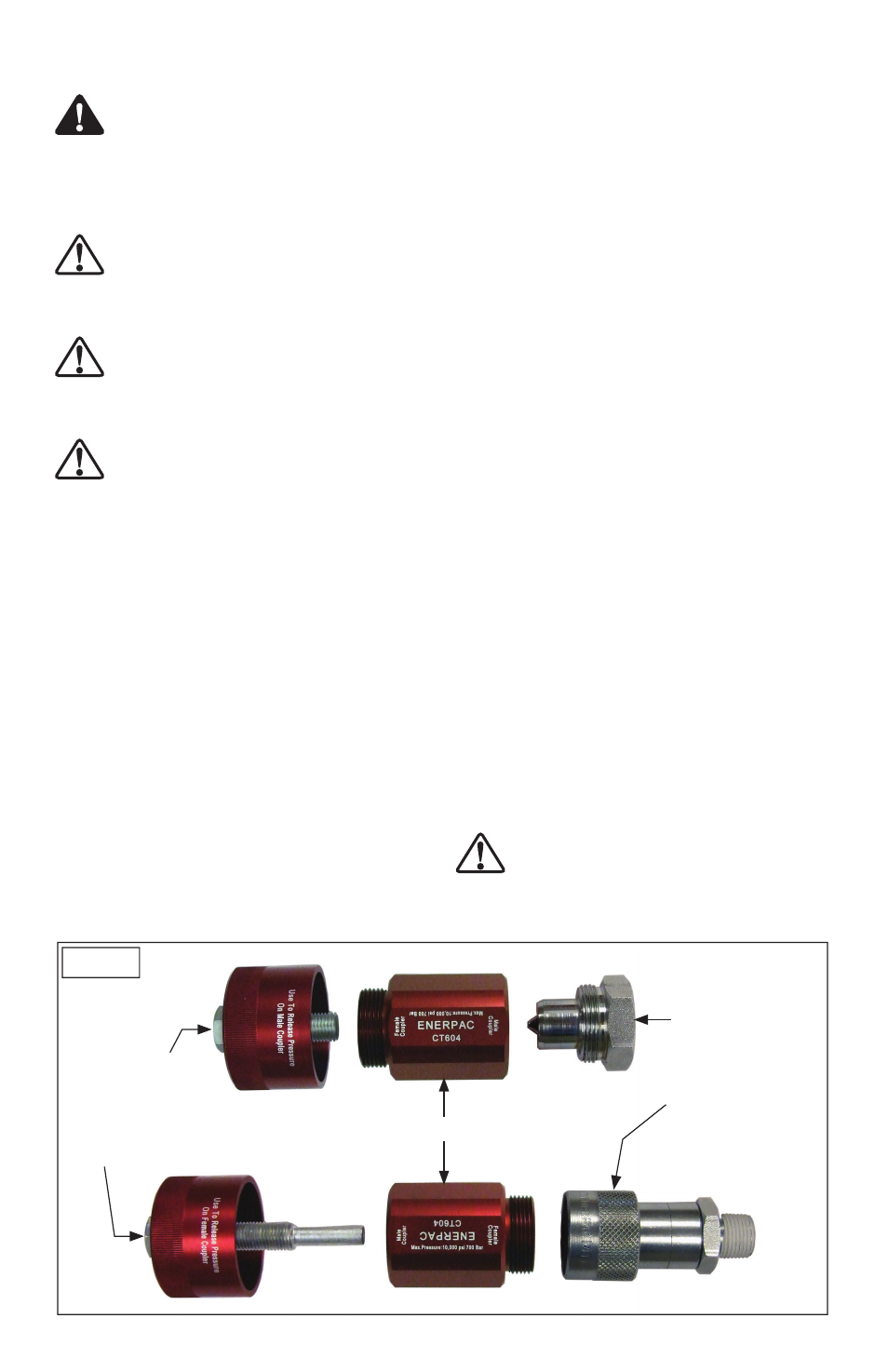
Note: Hand-tighten the bleed tool main body onto
the coupler half as described in steps 4 and 5. See
Figure 1, below.
Note: The bleed tool main body is marked “male
coupler” on one end and “female coupler” on the
other. Be sure to use the proper end.
4. If bleeding a male coupler half: Thread the bleed
tool main body onto the male coupler half and
tighten it hand-tight.
5. If bleeding a female coupler half: Thread the bleed
tool main body into the retaining collar of the
female coupler half. Tighten the retaining collar
hand-tight.
6. The bleed tool includes two cap/bolt assemblies
as shown in Figure 1, below. Be sure to use the
correct one:
• For MALE coupler halves, use the cap/bolt assem-
bly with the SHORT bolt.
• For FEMALE coupler halves, use the cap/bolt as-
sembly with the LONG bolt.
Note: Before proceeding, ensure that the cap is tight
on the bolt.
7. Thread the cap/bolt assembly into the bleed tool
main body. Slowly turn the cap/bolt assembly
clockwise until the coupler check ball opens and
hydraulic pressure is relieved. If necessary, use an
adjustable wrench on the bolt.
Note: When the cap/bolt assembly is tightened,
pressurized hydraulic oil will fl ow through the bleed
tool main body and into the cap. Allow any excess oil
to drain into a suitable container.
8. Remove coupler half, main body and cap/bolt
assembly from the hydraulic device (manifold,
cylinder, etc.) as a complete unit. Important: Keep
bleed tool parts installed on coupler while it is be-
ing loosened and removed.
9. Disassemble bleed tool components from the
coupler half. Clean bleed tool components and
store in provided container.
CAUTION: Discard the coupler half removed
in the previous steps. Never attempt to repair
or reuse a worn or damaged coupler!
Long Cap/Bolt Assy
(use with female coupler halves)
Short Cap/Bolt Assy
(use with male
coupler halves)
Main Body
Male Coupler Half
Female Coupler Half
Figure 1