Feedback and control cable assemblies, Main feedback cable (feedback a) – ElmoMC ExtrIQ Digital Servo Drives-Falcon User Manual
Page 27
Falcon Installation Guide
Installation
MAN-FALIG (Ver. 1.502)
27
“Smart” Control Supply Options:
•
Internal DC-to-DC converter that allows operation from DC power (no need for an auxiliary
external 24 VDC supply for normal operation).
•
24 VDC (13 V min to 40 V max) supply for backing up the control parameters if DC power is
shut off.
3.4.4.
Feedback and Control Cable Assemblies
The Falcon features easy-to-use D-Sub type connections for all Control and Feedback cables.
Instructions and diagrams describing how to assemble those cables are presented below.
1.
Use 24, 26 or 28 AWG twisted-pair shielded cables (24 AWG cable is recommended). For
best results, the shield should have aluminum foil covered by copper braid.
2.
Use only a D-Sub connector with a metal housing.
3.
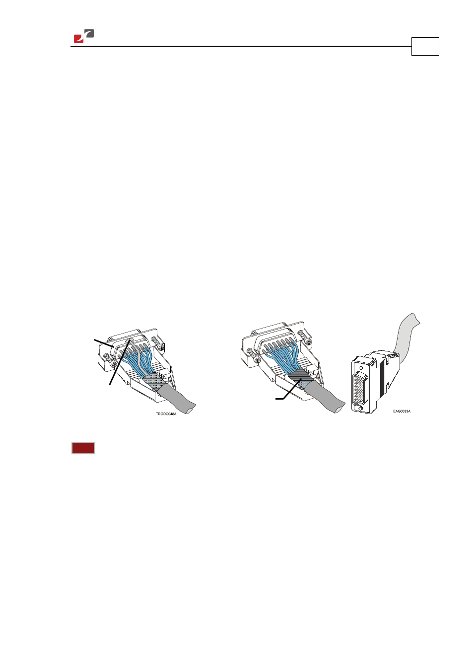
Ideally, solder the drain wire to the connector body as shown in Figure 8.
However, the shield may also be attached without soldering, as long as the braid shield is in
tight contact with the metal housing of the D-type connector.
4.
On the motor side connections, ground the shield to the motor chassis.
5.
On controller side connections, follow the controller manufacturer’s recommendations
concerning the shield.
Figure 8: Feedback and Control Cable Assemblies
Note:
All D-Sub type connectors used with the Falcon should be assembled in this way.
3.4.5.
Main Feedback Cable (FEEDBACK A)
The main feedback cable is used to transfer feedback data from the motor to the drive.
The Falcon accepts the following as a main feedback mechanism:
•
Incremental encoder only
•
Incremental encoder with digital Hall sensors
•
Digital Hall sensors only
•
Interpolated Analog (Sine/Cosine) encoder (option)
•
Resolver (option)
•
Tachometer & Potentiometer
Connector
body
Drain wire
soldered to
the metal
housing
Make sure that the
braid shield is in tight
contact with the metal
housing