Integrating the gold hornet on a pcb, Grounds and returns – ElmoMC ExtrIQ Gold Line Servo Drives-Gold Hornet User Manual
Page 33
Gold Hornet Installation Guide (EtherCAT and CAN)
Installation
MAN-G-HORIG-E (Ver. 1.007)
33
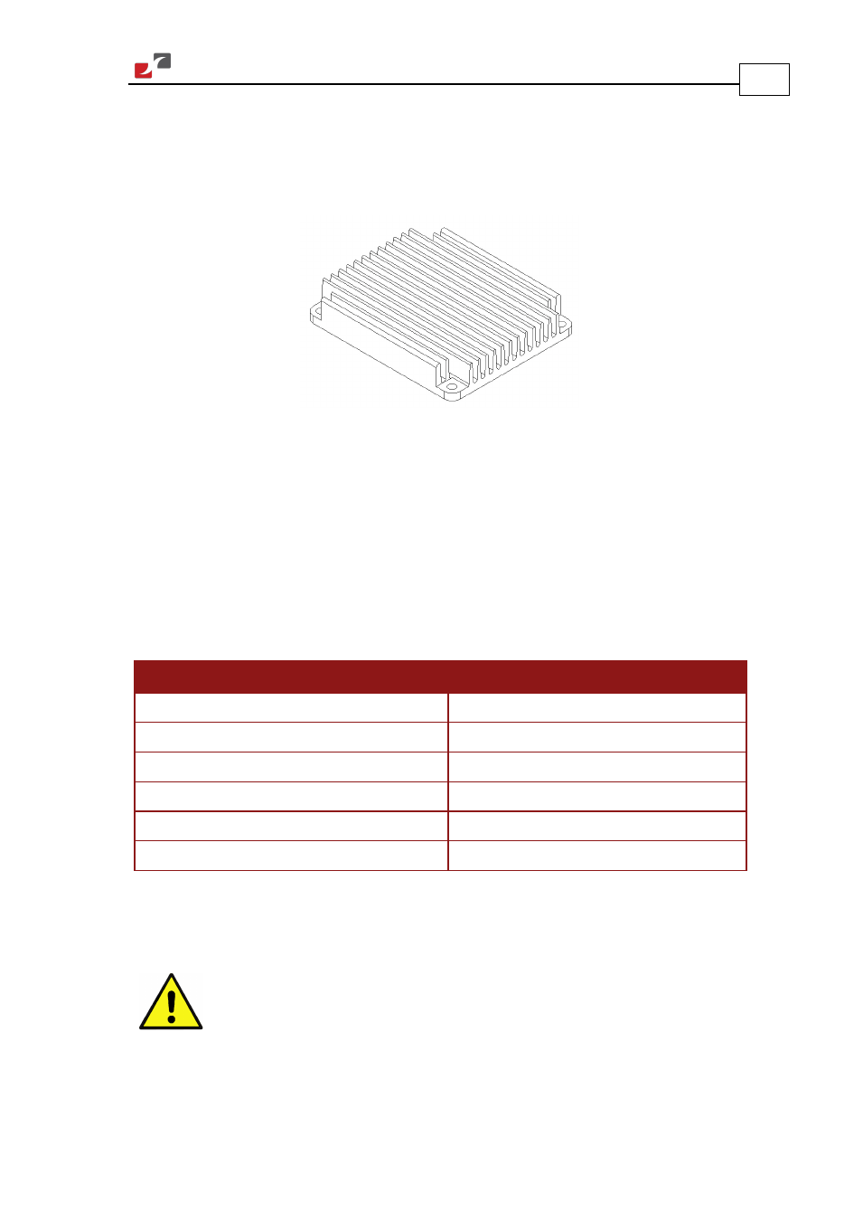
When the Gold Hornet is not connected to a metal chassis, the application’s thermal profile
may require a solution for heat dissipation due to insufficient air convection. In this case, we
recommend that you connect an external heat sink. Elmo has an external heat sink (Catalog
number: WHI-HEATSINK-2) that can be ordered for this purpose, see Figure 3 below.
Figure 3: Gold Hornet External Heat Sink
4.5. Integrating the Gold Hornet on a PCB
The Gold Hornet is designed to be mounted on a PCB, either by soldering its pins directly to the
PCB or by using suitable socket connectors. Refer to the Gold Line Whistle Design Guide MAN-
G-WHIIDG for further information.
4.5.1.
Grounds and Returns
The returns in each functional block are listed below:
Functional Block
Return Pin
Power
PR (Power Return)
Internal Switch Mode P.S.
PR (Power Return)
Analog input return
ANLRET (J2/20)
Common return
COMRET (J2/25,31,32,43,46; J1/23)
STO safety signal return
STO_RET (J1/10)
Input Return
IN_RET (J1/3)
Table 8: Grounds and Returns
The returns above are all shorted within the Gold Hornet in a topology that results in optimum
performance.
Caution:
Follow these instructions to ensure safe and proper implementation. Failure
to meet any of the below-mentioned requirements can result in drive,
controller or host failure.
1.
When wiring the traces of the above functions, on the Integration Board, the Returns of
each function must be wired separately to its designated terminal on the Gold Hornet. DO