Digital inputs and outputs – ElmoMC Gold Line Digital Servo Drives-Gold Tuba User Manual
Page 50
Gold Tuba Installation Guide
MAN-G-TUBIG-EC (Ver. 1.201)
50
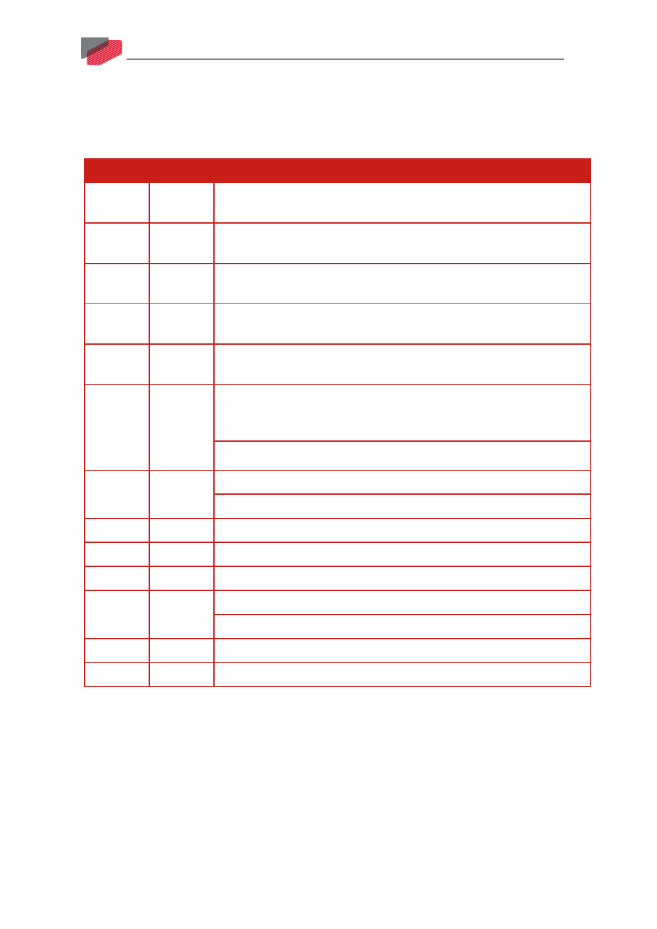
7.9. Digital Inputs and Outputs
The following table lists the Gold Tuba digital input and output pin assignments.
Refer to Chapter 11 in the in the MAN-G-Panel Mounted Drives Hardware manual for full details.
I/O Pins Signal
Function
1
IN1
High speed programmable input 1 (event capture, home, general
purpose, RLS, FLS, INH, PWM & direction input, pulse & direction input)
2
IN2
High speed programmable input 2 (event capture, home, general
purpose, RLS, FLS, INH, PWM & direction input, pulse & direction input)
7
IN3
High speed programmable input 3 (event capture, home, general
purpose, RLS, FLS, INH, PWM & direction input, pulse & direction input)
8
IN4
High speed programmable input 4 (event capture, home, general
purpose, RLS, FLS, INH, PWM & direction input, pulse & direction input)
11
IN5
High speed programmable input 5 (event capture, home, general
purpose, RLS, FLS, INH, PWM & direction input, pulse & direction input)
12
IN6
High speed programmable input 6 (event capture, home, general
purpose, RLS, FLS, INH, PWM & direction input, pulse & direction input)
or
STO OUT Collector in the O version
6
INRET1-6
Inputs 1 to 6 return for the S/T version
Positive input 1 to 6 for the H version
3
OUT1
Programmable output 1
4
OUT2
Programmable output 2
5
OUT3
Programmable output 3
13
OUT4
Programmable output 4 or
STO OUT Emitter in the O version
10, 15
VDD
Supply for out 1-4
9, 14
VDDRET
Supply return for out 1-4