Digital inputs and outputs (p4) – ElmoMC Gold Line Digital Servo Drives-Gold Cello User Manual
Page 43
Gold Cello Installation Guide
MAN-G-CELIG (Ver. 1.201)
||Digital Inputs and Outputs (P4)
43
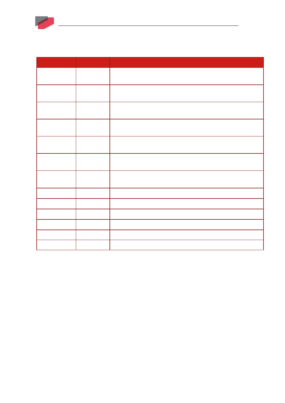
6.9. Digital Inputs and Outputs (P4)
Refer to Chapter 11 in the in the MAN-G-Panel Mounted Drives Hardware manual for full details.
I/O Pins (P4) Signal
Function
1
IN1
Programmable digital
input 1 (event capture, home, general purpose,
RLS, FLS, INH, PWM & direction input, pulse & direction input)
2
IN2
Programmable digital
input 2 (event capture, home, general purpose,
RLS, FLS, INH, PWM & direction input, pulse & direction input)
7
IN3
Programmable digital
input 3 (event capture, home, general purpose,
RLS, FLS, INH, PWM & direction input, pulse & direction input)
8
IN4
Programmable digital
input 4 (event capture, home, general purpose,
RLS, FLS, INH, PWM & direction input, pulse & direction input)
11
IN5
Programmable digital
input 5 (event capture, home, general purpose,
RLS, FLS, INH, PWM & direction input, pulse & direction input)
12
IN6
Programmable digital
input 6 (event capture, home, general purpose,
RLS, FLS, INH, PWM & direction input, pulse & direction input)
6
INRET1-6
Programmable inputs 1 to 6 return for the standard version
Programmable positive input 1 to 6 for the Sink version
3
OUT1
Programmable output 1
4
OUT2
Programmable output 2
5
OUT3
Programmable output 3
13
OUT4
Programmable output 4
10, 15
VDD
Supply for out 1-4
9, 14
VDDRET
Supply return for out 1-4