Port a and port b (p1) – ElmoMC Gold Line Digital Servo Drives-Gold Drum Ver 1_400 D-Sub connectors User Manual
Page 30
Gold Drum (D-Sub Connectors) Installation Guide
MAN-G-DRUM(DTYPE)IG-EC (Ver. 1.400)
||Port A and Port B (P1)
30
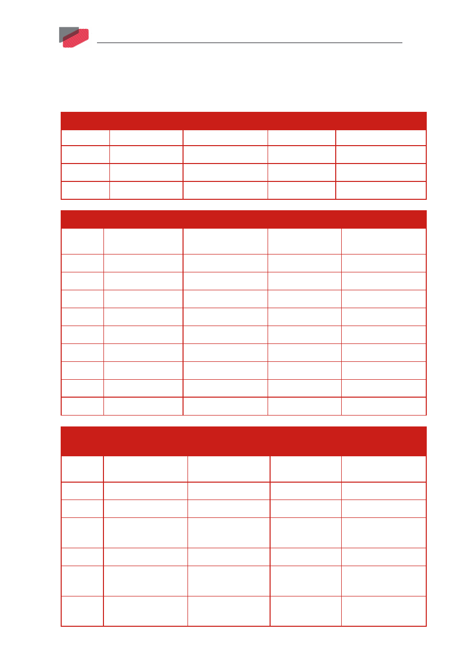
9.9. Port A and Port B (P1)
The Gold Drum Port A and Port B connector is a D-Type connector with 26 high density female pins.
See Section 10.3 and 10.4 in the manual: MAN-G-Panel Mounted Drives Hardware for full details.
Common Pins and their Signals
Pin (P1)
Signal
Function
Signal
Function
1,6,10,15 +5V
Encoder +5V supply
+5V
Encoder +5V supply
5, 14, 25, 26 COMRET
Common Return
COMRET
Common Return
24
Not Connected
Not Connected
Not Connected
Not Connected
Port A
Incremental Encoder
Absolute Serial Encoder
Pin on
P1
Signal
Function
Signal
Function
11
PortA_ENC_A+
Channel A+
ABS_CLK+
Abs encoder clock +
2
PortA_ENC_A-
Channel A-
ABS_CLK-
Abs encoder clock -
12
PortA_ENC_B+
Channel B+
ABS_DATA+
Abs encoder data +
3
PortA_ENC_B-
Channel B-
ABS_DATA-
Abs encoder data -
13
PortA_ENC_INDEX+ Index+
Reserved
Reserved
4
PortA_ENC_INDEX-
Index-
Reserved
Reserved
19
HA
Hall sensor A
HA
Hall sensor A
20
HB
Hall sensor B
HB
Hall sensor B
21
HC
Hall sensor C
HC
Hall sensor C
Port B
Incremental or
Interpolated Analog Encoder
Resolver
Pin on
P1
Signal
Function
Signal
Function
16
PortB_ENC_A+/SIN+ Channel A+ / Sine+
SIN+
Sine+
7
PortB_ENC_A-/SIN-
Channel A- / Sine-
SIN-
Sine-
17
PortB_ENC_B+/COS+ Channel B+ /
Cosine+
COS+
Cosine+
8
PortB_ENC_B-/COS- Channel B- / Cosine- COS-
Cosine-
18
PortB_ENC_INDEX+
Index+
RESOLVER_OUT+ Vref f=1/TS, 50 mA
Max.
9
PortB_ENC_INDEX-
Index -
RESOLVER_OUT- Vref complement
f= 1/TS, 50 mA Max.