Caution – Elkhart Brass Stinger RF8297 User Manual
Page 9
6
to the motor. As soon as the control switch is released, the circuit resets to allow
subsequent operation of the monitor.
Caution:
Any modification of the enclosure will destroy the NEMA 4 rating and will void the
warranty coverage of the Transmitter.
The following additional functions/features are provided in the RF Receiver/Control
Module:
Reverse Polarity Protection: If battery connections are reversed, this
feature prevents power from being applied to circuits, and prevents
damage to electronic components.
Circuit Board Moisture Protection: The circuit board and circuit components
are protected from moisture by an acrylic resin conformal coating. All relays
have sealed covers.
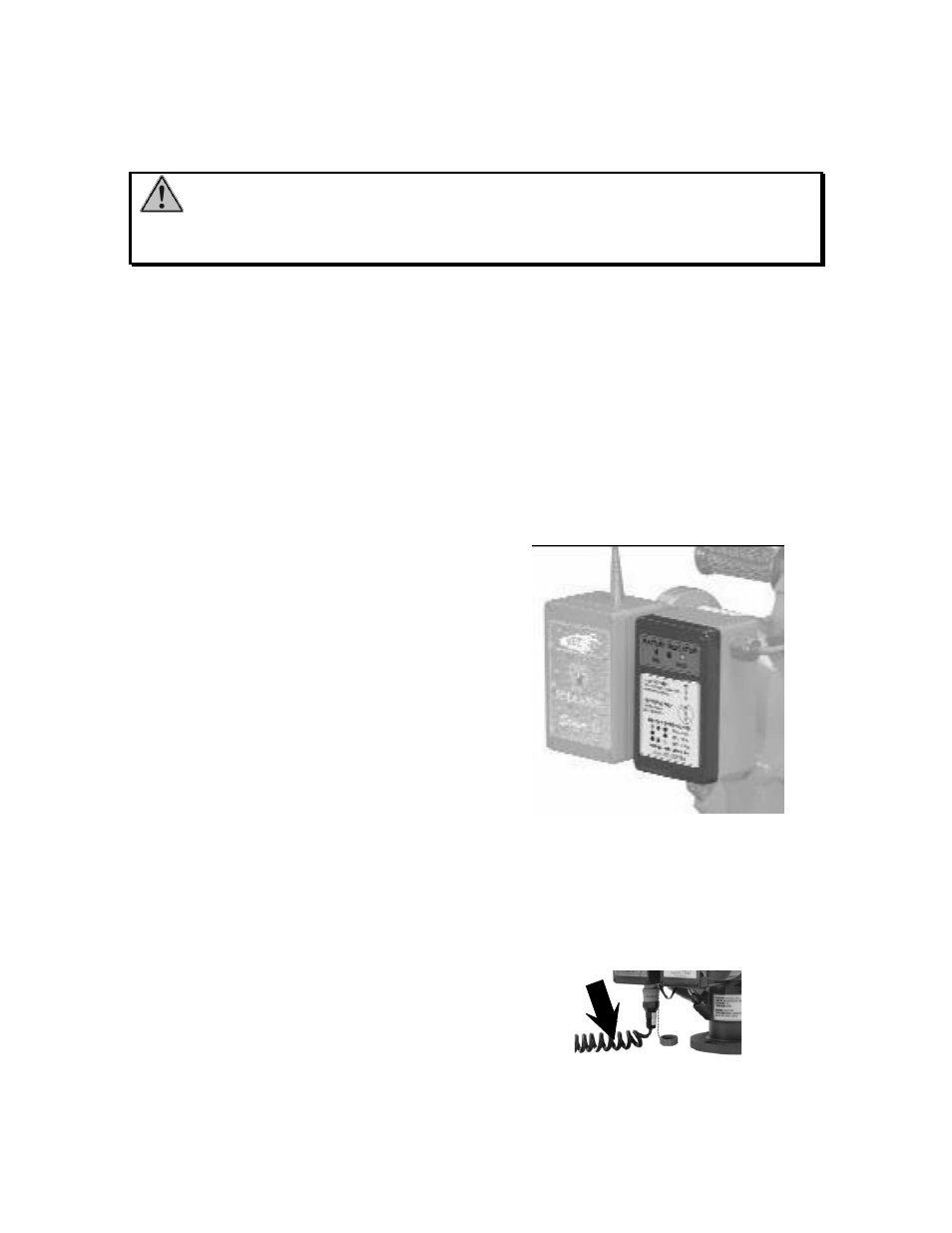
Battery Enclosure (See Figure 6)
The battery enclosure contains a 5 A/H
lead-acid
battery,
battery
charging
circuitry, and an LED battery charge
status indicator. This indicator displays
the source of power and the amount of
charge on the battery. A steady LED
means that truck power is connected and
the battery is charging. A flashing LED
signifies
that
truck
power
is
disconnected. A green LED signifies
80% to a full charge of the battery. A
yellow LED shows a 40%-80% charge
of the battery. A red LED signifies a
20% - 40% charge. If one LED is on
solid indicating a charging operation and
then all three LEDs blink; this means
that the charging voltage is less than the
battery voltage.
Figure 6
Battery Enclosure
Power Cable (See Figure 7)
The power cable (P/N 36846000)is a
three conductor coiled self-retracting
cable that provides for battery charging,
and allows operation of the monitor as a
deck gun while powered by the vehicle
electrical system. A bayonet style
connector allows convenient attachment
and removal of the cable from the power
receptacle located on the bottom of the
RF Receiver/Control Module. The
monitor control processor senses the
presence or absence of the power cable,
and thus determines the appropriate
allowable up-down travel range.
Figure 7
Power Cable