Iii. system component descriptions, A. 8297 rf upper monitor, System – Elkhart Brass Stinger RF8297 User Manual
Page 7: Component, Descriptions, Warning
4
III.
SYSTEM
COMPONENT
DESCRIPTIONS
A. 8297 RF Upper Monitor
The 8297 Stinger RF
®
Portable Monitor is a lightweight dual-purpose monitor. The
highly efficient cast aluminum waterway contains a central vane to minimize large-scale
turbulence and provide superior fire streams. The patented break-apart swivel joint
allows one upper assembly to be used with either of two truck mount adapters or one of
the many portable bases. Nozzle stream direction is controlled by two permanent magnet
type gear motors, one controlling rotation about the axis of the water inlet, and the other
controlling nozzle elevation and depression. The maximum monitor flow capacity is
1250 gallons per minute with most base adapters (the clappered Siamese inlet is rated at
1000 GPM).
Stinger RF
®
monitors are normally supplied with the 282A stream shaper and the SM-
1250E constant pressure (automatic) type master stream nozzle. The ST-194-A Stacked
Tip combination is also available for use with the Stinger RF
®
.
The following additional features are also provided in the Stinger RF
®
monitor:
Twist Release Handle and Lock Pin
The twist release handle makes a convenient carrying handle for both the Stinger RF
®
upper and the Stinger RF
®
with a portable base attached. It also provides for a quick
conversion from the deck mode to portable base mode. The lock pin ensures that the user
does not accidentally activate the twist release handle while carrying the Stinger RF
®
attached to the portable base.
Elevation Stop
The electronic elevation stop automatically limits the nozzle to a minimum elevation of
30
when in portable mode.
Warning:
Using the Up-Down over-ride while in portable mode can cause
serious injury or death to nearby personnel. Use extreme caution when using this
feature. The minimum elevation angle should be no less than 30
, and the portable base
must be securely anchored using the attached strap.
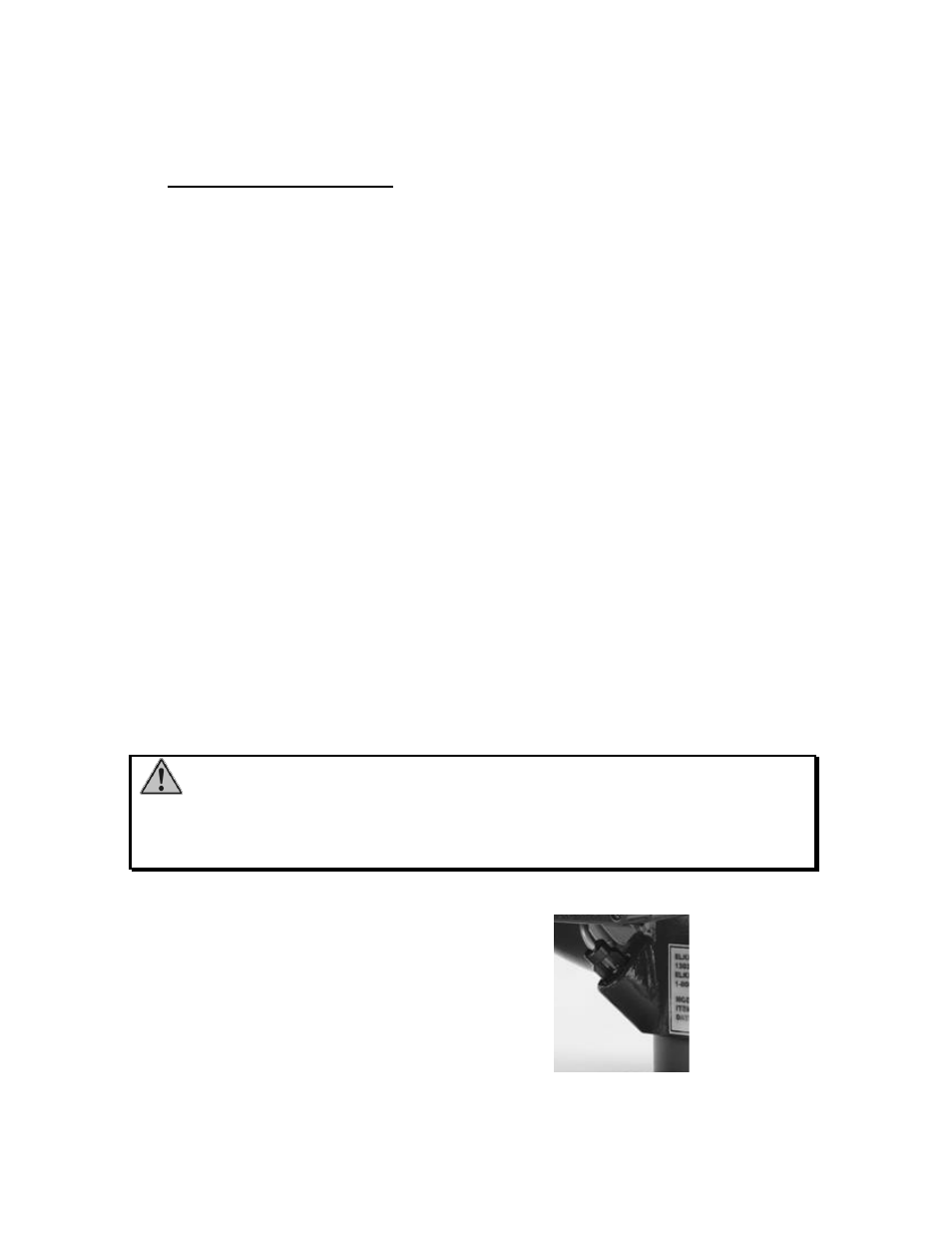
Latch Pin Visual Indicator (See Figure 4)
The visual indicator is used to
quickly determine when latch pins
are engaged. When the latch pins are
properly engaged, no part of the pins
should be visible in the indicator
cutout of the latch pin cap.
Figure 4
Latch Pin