Det-Tronics U7602B-P Unitized UV Flame Detector/Controller User Manual
Page 12
NOTE
The wiring procedures in this manual are intend-
ed to ensure proper functioning of the device
under normal conditions. However, because of
the many variations in wiring codes and regula-
tions, total compliance to these ordinances can-
not be guaranteed. Be certain that all wiring
complies with applicable regulations that relate to
the installation of electrical equipment in a haz-
ardous area. If in doubt, consult a qualified offi-
cial before wiring the system.
1. Mount the bulkhead and mounting bracket assem-
bly of the detector/controller. See Figure 7 for
dimensions. The mounting surface must be free
of vibration and suitable to receive 1/4 inch (M6)
screws with a length of at least 1 inch (25 mm).
9
95-8239
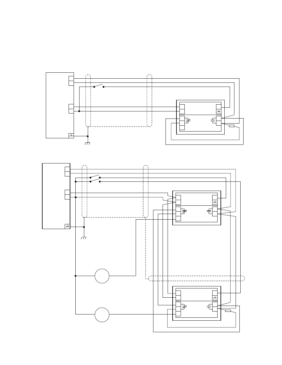
FIRE ALARM PANEL
ALARM
INPUT
U7602
EOL
REGISTER
CURRENT
FIRE RELAY IS NORMALLY OPEN.
FAULT RELAY IS NORMALLY CLOSED
AFTER POWER-UP TIME DELAY,
IN A NO FAULT CONDITION.
FAULT
NC
FIRE
NO
5
4
3
1
2
TB1
TB3
*
*
oi
TEST
+
–
oi
+
–
A1489
FIRE ALARM PANEL
ALARM
INPUT
U7602
U7602
EOL
REGISTER
CURRENT
EXTERNAL CURRENT METER
(IF NEEDED)
FIRE RELAY IS NORMALLY OPEN.
FAULT RELAY IS NORMALLY CLOSED
AFTER POWER-UP TIME DELAY,
IN A NO FAULT CONDITION.
FAULT
NC
FIRE
NO
FAULT
NC
FIRE
NO
0 TO 1 MA
0 TO 1 MA
5
4
3
5
4
3
1
2
1
2
TB1
TB1
TB3
CURRENT
M
M
*
*
oi
TEST
+
–
oi
oi
+
–
+
–
A1488
TB3
*
Figure 13—Typical Wiring Diagram
Figure 14—Typical Multiple Unit Configuration with End of Line Resistors