Mrc5000 setup (optional), Table 5. mrc 5000 settings, Schematics – Despatch RAD Series User Manual
Page 36
A
PPENDICES
RAD Oven Series Owner
’s Manual
36
Version 1
Copyright © 2012 by Despatch Industries.
All rights reserved. No part of the contents of this manual may be reproduced, copied or transmitted in any form or by any
means including graphic, electronic, or mechanical methods or photocopying, recording, or information storage and
retrieval systems without the written permission of Despatch Industries, unless for purchaser's personal use.
8.2. MRC5000 Setup (Optional)
Refer to instructions provided recorder manufacturer for more
specific installation notes.
Temperature is retransmitted to the MRC5000 recorder from the controller. Set up the recorder
by:
1. Ensure hardware jumper JU1 is in place for the 5 VDC setting (Refer to MRC5000 Manual
included).
2. Move
MODE
to
PROG/TEST/CAL
to display
Prog
.
3. Press ▼ twice to display
Inps
. Move to each Parameter Code using ▼or ▲. Adjust each
Parameter Code using the settings in Table 5.
4. After adjusting all settings, move
MODE
to
RUN
. Display on both the recorder and controller
should read the same.
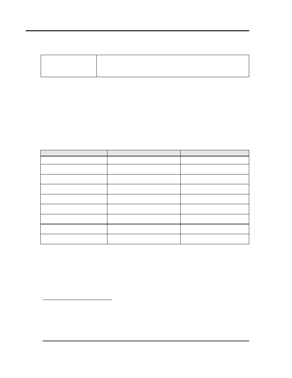
Table 5. MRC 5000 Settings.
Parameter Code
Degrees C
Degrees F
Inps
17
17
Icor
0
0
diSP
On
On
dPOS
0
0
EUU
400
752
EUL
4
0
32
ChUP
400
800
5
ChLO
0
0
DFF
1
1
8.3. Schematics
The following pages contain electrical and mechanical schematics for the RAD2-13, 2-19 and 2-
35 ovens.
4
These values must match the settings
RetOutLo
and
RetOutHi
on the Protocol 3 Control page. For
example, if
RetOutLo
is 32,
EUL
must read 32.
5
Change 0-400 chart paper to 0-800 chart paper. Depending on the equipment used, 0-600 paper may be
used if the maximum temperature is 260°C (500°F).