Service – Danuser 9000 Postmaster/SlabBlaster User Manual
Page 21
21
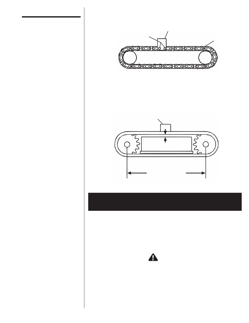
STEP 8: Position the new drive chain around the frame and sprockets, and install the pick-
up link. Drive pins through the pick-up link and chain, weld connector pin holes
shut, and grind weld flush.
STEP 9: Slide the bearings back out and tighten the bolts. Measure the distance between
the two shafts. This measurement must be the same on both sides.
STEP 10: Check the tension of the drive chain by placing a 50 lb. weight (or the upper head
assembly) on the center of the chain, midway between the upper and lower
sprocket. Deflection with the weight placed on the chain should be 3/16”. Tighten
or loosen chain as needed.
STEP 1: Remove the safety catch pin from the top of the frame. Insert a hook into the chain
links welded to the top of the hammer, and lift out the hammer with a hoist,
forklift, or another vehicle. Lay the hammer on the ground.
STEP 2: Disconnect the hydraulic hoses from the vehicle auxiliary hydraulics, remove them
from the quick attach plate hose holder, and reconnect the hydraulic hoses to the
vehicle.
STEP 3: Raise the Postmaster in the air, and tilt it forward 90°. Watch for any obstructions
or pinching of hydraulic hoses.
STEP 4: Shut off the vehicle engine.
Service
(continued)
CHANGING THE POSTMASTER UPPER HEAD ASSEMBLY
OR CHANGING THE COLLAR
C A U T I O N
Do not tilt the Postmaster with the hydraulic hoses routed
through the quick attach plate hose holder. Damage to the
hydraulic hoses will occur.
Pick-Up Link
Drive Chain
Drive pin through pick-up link
and chain. Weld connector
pin holes shut. Grind
welds flush.
50# Weight
3/16" Deflection
Approx. 34-5/8"
(Each side must be equal length.)