Operation, Assembly & installation – Danuser 9000 Postmaster/SlabBlaster User Manual
Page 15
1
STEP 11: Lower the Postmaster onto the post approximately 24 inches. Reposition the
vehicle using the guide chain as a plum line.
STEP 12: Turn on the auxiliary hydraulics in the forward position. This will open the jaws,
swing the Grapple out of the way, and start the hammer.
STEP 13: The Postmaster can now be activated by turning the auxiliary hydraulics to
the forward position. Drive the post into the ground until the post guide is
approximately 6 inches above the rubber cushion. If needed, shut off the auxiliary
hydraulics and reposition the vehicle to ensure the post is driven into the ground
straight.
STEP 14: Repeat STEPS 11 and 13 until the post has been driven to the desired depth.
STEP 15: Shut off the auxiliary hydraulics, raise the Postmaster until the post is cleared,
and move to the next post.
STEP 1: Grease the 2 grease zerks on the hydraulic cylinder.
STEP 2: Attach the wiring harness to the diverter valve on the Postmaster.
STEP3: Route the wires along the hoses to the vehicle, and secure them with zip-ties.
Operation
(continued)
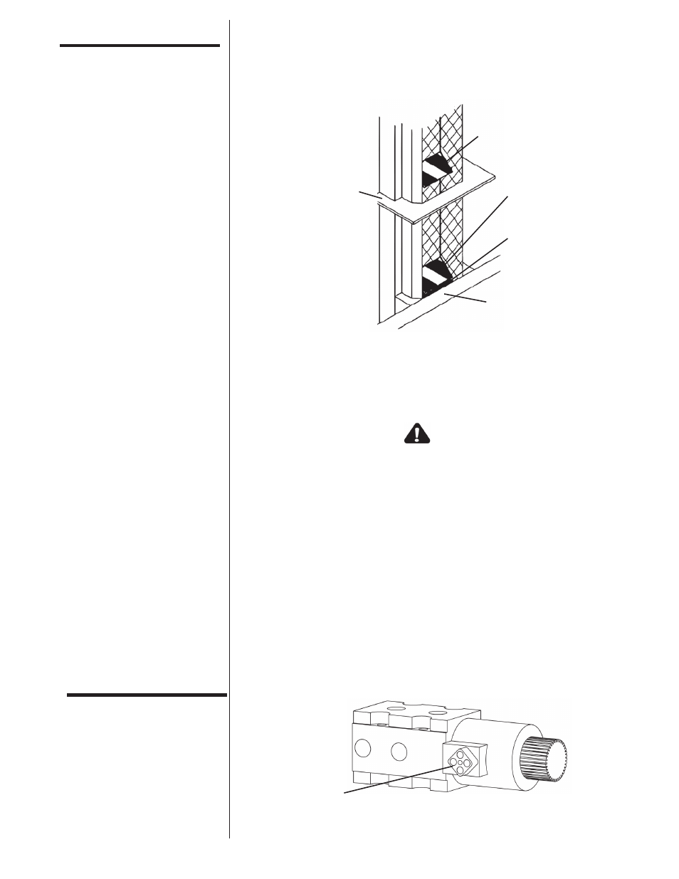
C A U T I O N
Failure to lower the Postmaster as the post guide nears the
rubber cushion will result in the hammer bottoming out.
Although occasional bottoming out of the hammer will give
the operator a jolt, it will not (under normal load conditions)
damage the Postmaster. However, repeated bottoming out
of the hammer will cause structural damage and excessive
wear to the Postmaster and vehicle lift arms.
Assembly &
Installation
Tilt
BACK OF POSTMASTER
Reinforcement Plate
Post Guide (when moved
6" above reinforcement plate)
Post Guide
(when moved up 2")
Rubber Cushion
Quick Attach Plate
Remove Cover