Comelit FT SBC 04 User Manual
Page 18
3323
4660C
12
34
56
78
ON
DIP
IT
EN
FR
NL
DE
ES
PT
IT
EN
FR
NL
DE
ES
PT
IT
EN
1
2
3
2A
2B
GROUP S.p.A.
FT SBC 04
18
Programmazione pulsanti con gruppo audio video Art. 4660C e moduli Art. 3323/3, 3323/4 e 3323/6.
Procedura valida anche per la programmazione dei moduli Art. 3063B e Art. 3064B cablati verso l’Art. 4660C tramite cavetto plug 4 poli.
AVVERTENZE:
• I moduli Art. 4660C funzionano normalmente come posto esterno
principale (segnalazione di occupato a tempo).
Per impostarli come posto esterno secondario (segnalazione di occupato
attiva per tutta la durata di impegno del montante) è necessario mettere
tutti i Dip switch del selettore su ON.
• Se all’atto della chiamata il posto esterno emette un tono di occupato
invece che la replica della suoneria significa che un’altra comunicazione è
già in atto verso un altro posto esterno.
•
In caso di cortocircuito persistente sulla linea bus il posto esterno
emette un tono di segnalazione intermittente.
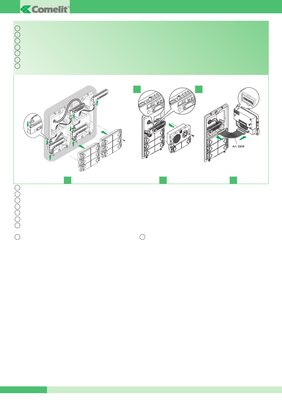
1 Connettere le morsettiere dei moduli Art. 3323/3, 3323/4 e 3323/6 (oppure
i moduli Art. 3063B e Art. 3064B) tra loro e con la morsettiera del gruppo
Art. 4660C utilizzando gli appositi cavetti. Inserire i moduli Art. 3323/3,
3323/4 e 3323/6 sulle relative morsettiere (Fig. 1).
2 Sulla morsettiera del modulo Art. 4660C collegare l’alimentazione su ~~,
spostare l’interruttore in posizione di programmazione (quadrato rosso)
(vedi Fig. 2A). Connettere la morsettiera al modulo Art. 4660C assemblato
come indicato precedentemente.
Attenzione i moduli Art. 3323/3, 3323/4 e 3323/6 da programmare,
devono essere già posizionati (Fig. 2).
Nota: per il collegamento tra la morsettiera e il modulo Art. 4660C in fase
di programmazione è possibile usare il cavetto Art. 3309 disponibile come
accessorio opzionale (Fig. 3).
3 Impostare il Dip switch posto sul retro del modulo Art. 4660C con lo
stesso codice assegnato al citofono o monitor, secondo la corrispondenza
descritta nella tabella di programmazione a pag. 21.
4 Premere il pulsante che si desidera associare alla chiamata del citofono.
L’avvenuta programmazione viene segnalata con un tono di conferma.
5
Al termine della programmazione riposizionare l’interruttore in
posizione di standby (quadrato bianco) (vedi Fig. 2B).
Button programming with audio/video unit Art. 4660C and modules Art. 3323/3, 3323/4 and 3323/6.
This procedure also applies when programming modules Art. 3063B and Art. 3064B wired to Art. 4660C by means of a 4-pole plug-in cable.
WARNING:
• Modules Art. 4660C normally function as the main external unit (timed
busy signal).
To set them as a secondary external unit (busy signal active for the whole
time the riser is in use), set all the selector DIP switches to ON.
• When a call is transmitted from the external unit, if a busy tone is heard
instead of the ringtone, this means communication with another external
unit is in progress.
•
In the event of a persistent short-circuit on the bus line, the external
unit emits an intermittent signalling tone.
1 Connect the terminal blocks of modules Art. 3323/3, 3323/4 and 3323/6
(or modules 3063B and 3064B) to each other and to the terminal block
of unit Art. 4660C using the special cables. Fit the modules Art. 3323/3,
3323/4 and 3323/6 to the corresponding terminal blocks (Fig. 1).
2 On the terminal block of module Art. 4660C, connect the power supply
to ~~ and set the switch to its programming position (red) (see Fig. 2A).
Connect the terminal block to module Art. 4660C assembled as indicated
above.
Warning - modules Art. 3323/3, 3323/4 and 3323/6, to be programmed,
must already be positioned (Fig. 2).
Note: For connection between the terminal block and module Art. 4660C
during the programming stage it is possible to use the cable Art. 3309,
available as an optional accessory (Fig. 3).
3 Set the Dip switch on the rear of the module Art. 4660C with the same
code assigned to the door-entry phone or monitor, in accordance with the
information provided in the programming table on page 21.
4 Press the button to be associated with the door-entry phone call. A tone
signal confirms the completion of programming.
5
After completing programming, set the switch back into standby
position (white) (Fig. 2B).
Programmation des boutons avec groupe audio vidéo Art. 4660C et modules Art. 3323/3, 3323/4 et 3323/6.
Procédure valable pour la programmation des modules Art. 3063B et Art. 3064B câblés vers l’Art. 4660C au moyen du câble plug 4 pôles.
Programmering drukknoppen met audio/video-unit art. 4660C en modulen art. 3323/3, 3323/4 en 3323/6.
Deze procedure geldt ook voor de programmering van de modulen art. 3063B en art. 3064B die naar art. 4660C bekabeld zijn met het kabeltje met 4 -polige plug.
Tastenprogrammierung der Audio/Video-Station Art. 4660C mit den Modulen Art. 3323/3, 3323/4 und 3323/6.
Diese Vorgehensweise gilt ebenfalls für die Programmierung der Module Art. 3063B und 3064B, die mit Art. 4660C über das Kabel mit 4 -poligem Stecker verbunden sind.
Programación de pulsadores con grupo audio vídeo art. 4660C y módulos art. 3323/3, 3323/4 y 3323/6.
Este procedimiento también es válido para programar los módulos art. 3063B y art. 3064B conectados al art. 4660C con un cable plug de 4 polos.
Programação dos botões com grupo áudio vídeo art. 4660C e módulos art. 3323/3, 3323/4 e 3323/6.
Procedimento igualmente válido para a programação dos módulos art. 3063B e art. 3064B com ligação ao art. 4660C com cabo adaptador de 4 pólos.