Fuses & power control – Carbolite VST 17/-- User Manual
Page 14
1700° Tube
14
LMF32C – 1.07
7.0 F
USES
&
P
OWER
C
ONTROL
7.1 Fuses
F1 & F2 - see the example circuit diagram.
F1
Supply Fuses:
Supply fuses are not fitted internally unless the furnace is also fitted with a supply cable; when
fitted they are of GEC Safeclip of the type shown.
Customers should fuse at the rating shown.
F2
Control Fuses: 2 Amp type F 30mm x 6mm
Thyristor Fuse:
Ferraz Protistor of the rating shown. Note that, unlike most fuses, protistor fuses
are correctly rated at a higher current than the thyristor they are protecting.
7.2 Power Control
The setting for the power limit parameter in the controller (
OP.Hi
) should be 100% for all models.
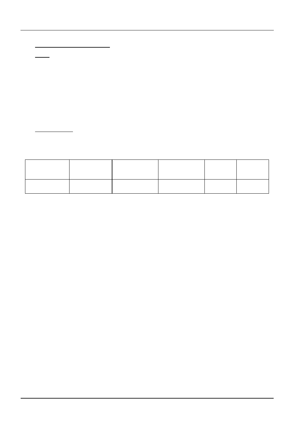
The thyristor stacks are set to the secondary (element) maximum currents given in the table.
Model
Phases
volts
supply fuse
rating
type
thyristor
fuse
rating
Current limit
(element
circuit)
VST 17/--/250
1-phase
220-240
25A
NS25
30A
75A